Valve device and method for injecting a gaseous fuel
a valve device and gaseous fuel technology, which is applied in the direction of fuel supply apparatus, special fuel injection apparatus, structural/machine measurement, etc., can solve the problems of inability to design the injector to be suitable for gaseous fuel injection, the response characteristic and the scope of control options, and the comparatively slow response characteristic of the hydraulic valve, etc., to achieve accurate valve needle position control, reduce the effect of valve li
- Summary
- Abstract
- Description
- Claims
- Application Information
AI Technical Summary
Benefits of technology
Problems solved by technology
Method used
Image
Examples
first embodiment
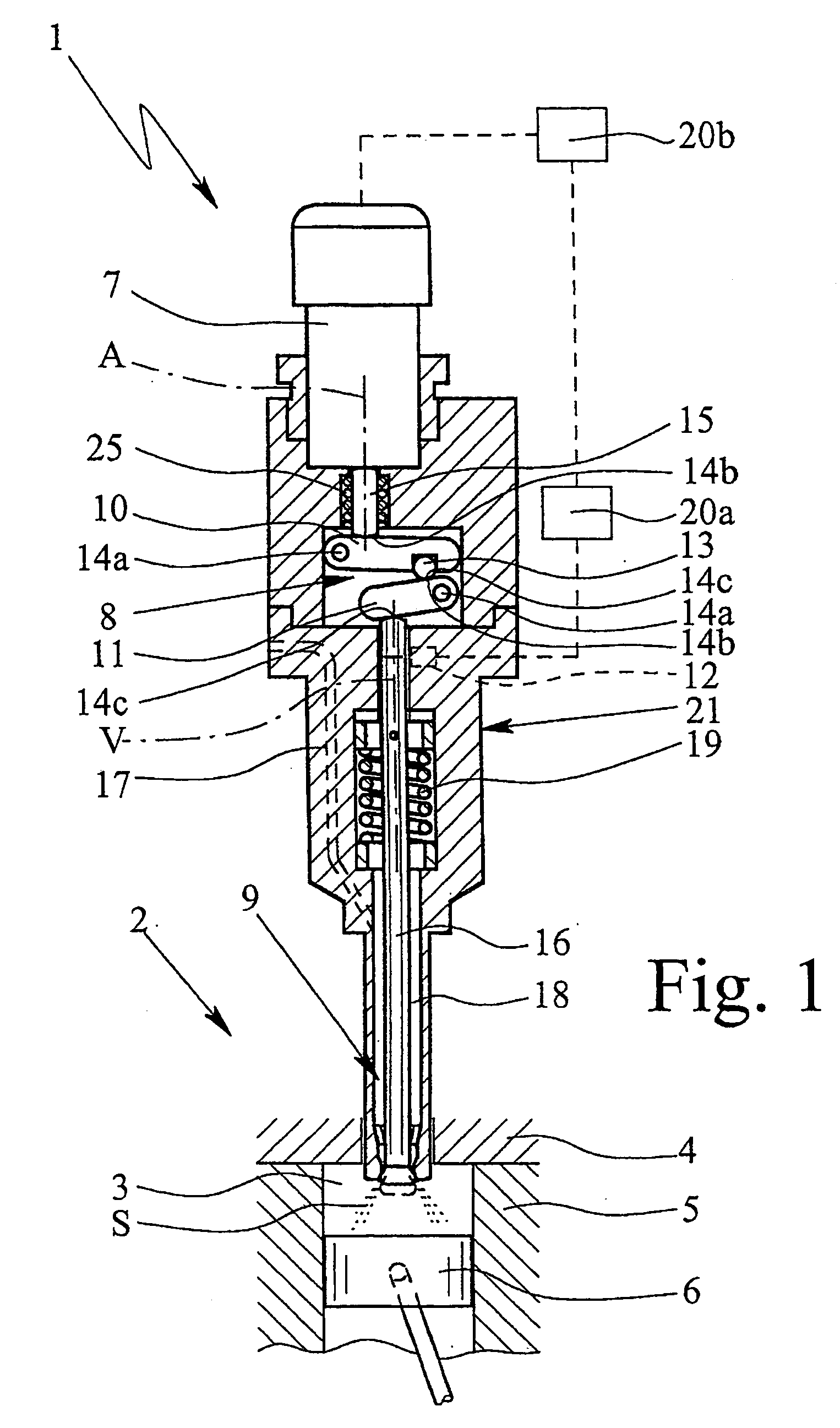
[0072] In the first embodiment, valve 9 is executed so that it opens outward, that is, towards combustion chamber 3.
[0073] In the illustrated embodiment, the fuel preferably is injected into combustion chamber 3 along a cone shape—in particular with an opening angle between 60° and 120°.
[0074] But if required, it is also possible to position a nozzle (not shown) with several passage openings at the end that projects into combustion chamber 3 in order to produce a corresponding number of fuel jets S that are directed in the desired directions.
[0075] Valve device 1 preferably comprises general housing 21, which can be a multi-part housing 21, as containment and / or mounting for integration of actuator 7, transmission device 8, valve 9, restoring device 19, the nozzle, sensor device 12, and / or signal processor 20a.
[0076] Further embodiments will be illustrated in the following with the help of FIGS. 2, 3, and 4. For simplification, sensor device 12, control device 20, and channel 17 ...
second embodiment
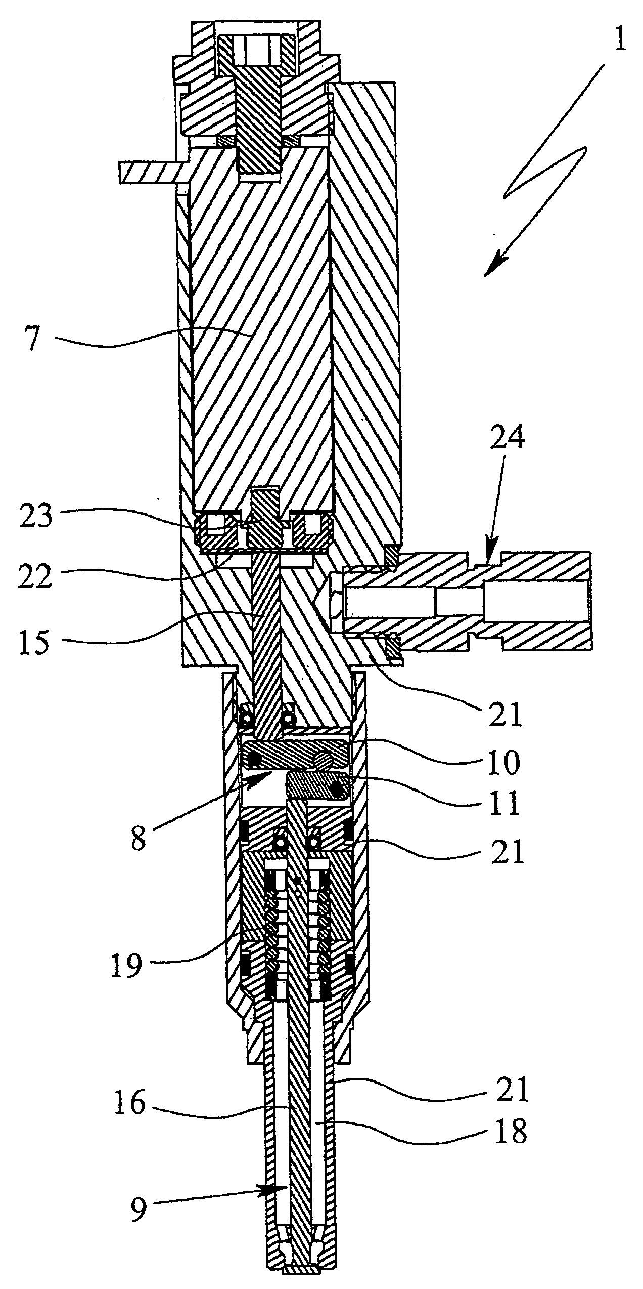
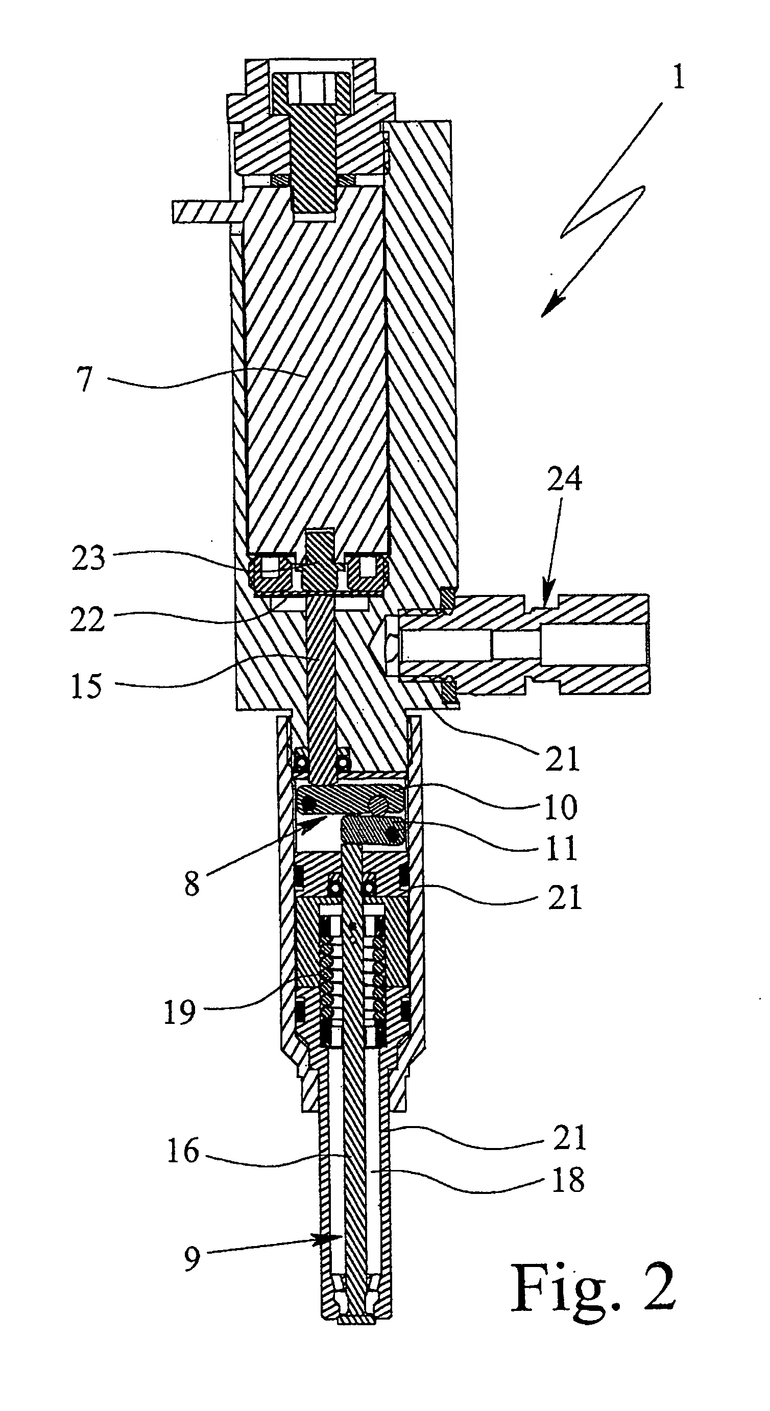
[0077] In valve device 1 shown in FIG. 2, actuator 7 is preferably enclosed and sealed gas-tight against transmission device 8, in particular by means of membrane 22. In the illustrated example, membrane 22 is installed or arranged between plunger 23 of actuator 7 and plunger 15 acting on transmission device 8.
[0078] According to the second embodiment, valve device 1 is equipped with lateral connection 24 to supply the fuel. Here as well, connection 24 communicates with interior space 18 of valve 9. As mentioned above, channel 17, as it is indicated in FIG. 1, is not shown.
[0079]FIG. 3 shows a sectional partial view of transmission device 8 of valve device 1 according to the second embodiment of FIG. 2. Transmission device 8 in this embodiment is fundamentally equivalent to the transmission device according to the first embodiment. FIG. 3 in particular illustrates the positions of support points 14a, contact points 14b, and output points 14c of levers 10 and 11.
[0080] Support poin...
third embodiment
[0082] The schematic sectional view of FIG. 4 shows valve device 1. Here as well, lateral connection 24 for supplying the fuel is provided.
[0083] The third embodiment differs in important respects from the first and second embodiments. In the third embodiment, valve 9 is executed as an inward-opening needle valve and accordingly the transmission device is executed slightly different. Unlike the first and second embodiments, in the third embodiment, the direction of motion, that is, the direction of valve lift, of actuator 7 is directionally opposite from the resulting motion of valve 9 and valve element 16. This is achieved by positioning output point 14c of first lever 10, and thus input point 14b of second lever 11, on the outside of support point 14a of second lever 11; that is, support point 14a of second lever 11 is positioned between contact point 14b and output point 14c of second lever 11.
[0084] Upon activation of actuator 7, both levers 10, 11 swing in the same direction o...
PUM
 Abstract
Description
Claims
Application Information
 - R&D
- Intellectual Property
- Life Sciences
- Materials
- Tech Scout
- Unparalleled Data Quality
- Higher Quality Content
- 60% Fewer Hallucinations
Browse by: Latest US Patents, China's latest patents, Technical Efficacy Thesaurus, Application Domain, Technology Topic, Popular Technical Reports.
© 2025 PatSnap. All rights reserved.Legal|Privacy policy|Modern Slavery Act Transparency Statement|Sitemap|About US| Contact US: help@patsnap.com


