System and method for controlling fuel vapor emission in a small engine

a technology of fuel vapor emission and system, which is applied in the direction of combustion air/fuel air treatment, non-fuel substance addition to fuel, condensed fuel collection/return, etc., can solve the problems of increasing the cost of engine manufacture, complexity and cost of reworking the fuel system of small engines,

Active Publication Date: 2007-06-05
EATON INTELLIGENT POWER LTD
View PDF13 Cites 21 Cited by
  • Summary
  • Abstract
  • Description
  • Claims
  • Application Information

AI Technical Summary

Benefits of technology

[0005]The present specification, drawings and claims describe a fuel system for a small engine including a fuel tank having an integrally formed, tank and filler tube with a non-venting cap for the filler tube and with the lower end of the filler tube set in the tank at a predetermined level to prevent completely filling the tank above the desired level and thereby providing a vapor dome above the liquid fuel in the tank. The tank includes a fill limiting vapor vent / tipping valve which has its vapor outlet connected to a storage canister which is connected to the engine air inlet for flow of vapor to the engine during operation. An atmosphere air purge vent is provided on the canister and in the described embodiments is connected to the engine filter permitting filtered air to be drawn into the canister during purge flow. The tank is formed with a vapor impermeable barrier which may include material such as HDPE with either ethylene vinyl alcohol (EVOH) interspersed therein, or polyamide interspersed therein. In one embodiment the fuel tank filler extends from a depressed area in the top of the tank wall such that the lower end of the filler tube is at a level lower than the top of the tank to thereby define a vapor dome. In an alternative embodiment the lower end of the filler tube is defined by an insert in the integrally molded filler tube with the lower end of the insert defining the desired fuel fill level.

Problems solved by technology

The requirement that the tank vent be sealed has caused additional complexity and cost in reworking small engine fuel systems to meet the vapor emission requirements, particularly because engines of this type are manufactured in very high volume and the tooling is of the permanent type and represents a significant expenditure.
Requirements for changes in design of the fuel system and fuel tanks will thus result in substantial increase in cost for the engine manufacture.

Method used


Image

  • System and method for controlling fuel vapor emission in a small engine
  • System and method for controlling fuel vapor emission in a small engine
  • System and method for controlling fuel vapor emission in a small engine

Examples


Embodiment Construction

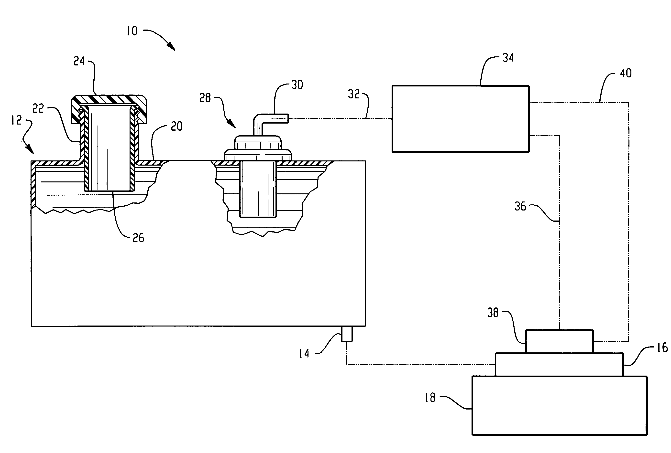
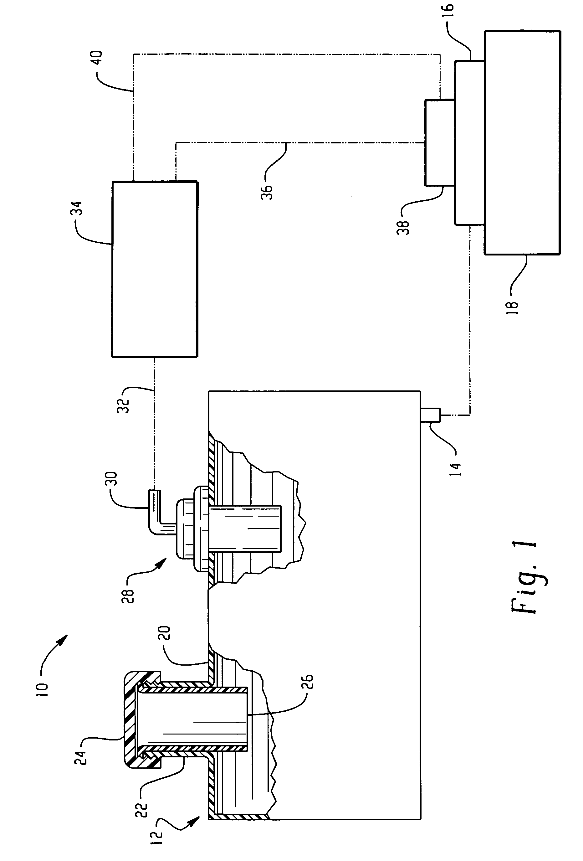
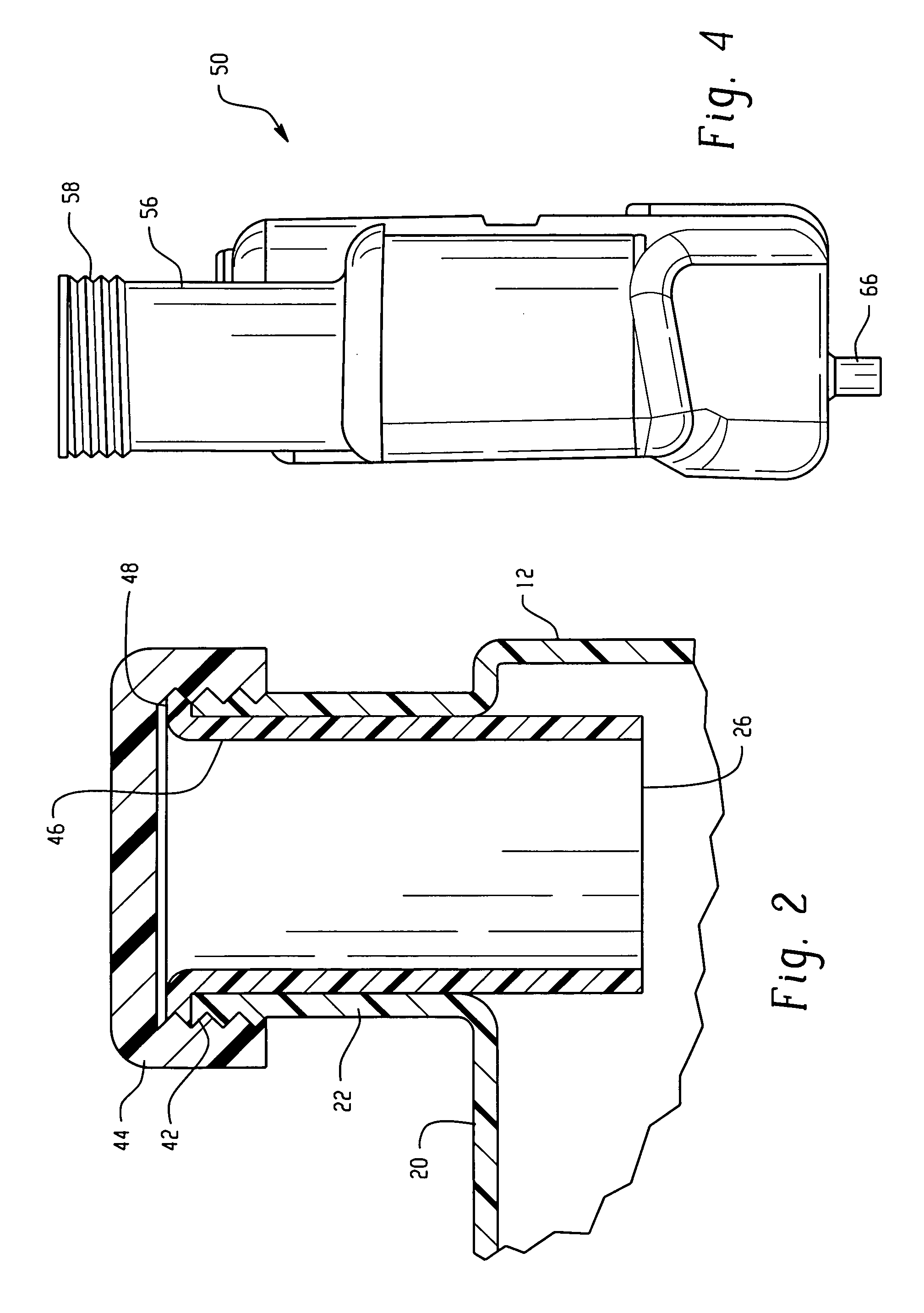
[0010]Referring to FIG. 1, a system for controlling fuel vapor emission in a small engine is indicated generally at 10 and includes an exemplary embodiment of a fuel tank indicated generally at 12 having a gravity feed fuel line 14 connected to the carburetor 16 of a small engine 18. The upper portion of the wall structure 20 of the tank has formed integrally therewith a fuel filler tube 22 which has a non-vented user removable closure cap 24 disposed on the upper end thereof. The lower end 26 of the filler tube extends inwardly of the tank to a predetermined desired level for reasons which will hereinafter be described in greater detail.

[0011]The upper wall structure 20 of the tank also has disposed therein a fill limiting vapor vent / tipping valve indicated generally at 28 which has a vapor vent outlet 30 which is connected along line 32 to a storage canister 34 which may contain adsorbent material. The storage canister 34 has a purge or vapor outlet connected along line 36 through...


PUM


Abstract

A small engine fuel system has a tank with an integrally formed filler tube having the lower end located at a level below the upper portion of the tank wall which is formed of vapor impermeable material which may include HDPE interspersed with EVOH or polyamide. In one exemplary embodiment the filler neck is disposed in a depression in the upper portion of the tank wall; and in another exemplary embodiment the filler tube has an insert which extends into the tank to a position below the upper portion of the tank wall to form a vapor space. The tank includes a fill limiting vapor vent / tipping valve with its outlet connected to a storage canister which outputs to the engine and which has an atmospheric air vent.

Description

BACKGROUND[0001]Small engines of less than 50 horsepower (37.4 kilowatts) are widely used in applications such as garden tractors, lawn mowers, portable generating sets and small boat marine applications. Such engines typically employ a fuel tank mounted proximate the engine and arranged for gravity feed of fuel from the tank to the engine carburetor, although in applications approaching 50 horsepower fuel pumps may be employed in certain applications.[0002]Heretofore, small engines have not been subject to fuel vapor emission requirements as are of motor vehicles; however, it has recently been mandated that small engines for such applications to have fuel systems which prevent vapor emission to the atmosphere both during engine operation and during periods of engine shut down. *Fuel tanks for small engines typically employ an open vent in the fuel filler cap for passage of make-up air as fuel is withdrawn during engine operation; and, to prevent pressure build up in the tank from f...

Claims


Application Information

Patent Timeline
Patent Type & Authority Patents(United States)
IPC IPC(8): F02M33/02
CPCB60K15/03504F02M37/20F02M25/089B60K15/03519E05C17/443E05Y2600/622E05Y2900/132
Inventor MILLS, VAUGHN K.
Owner EATON INTELLIGENT POWER LTD
Why Eureka
Try Eureka