Connector having an improved locking structure

a technology of locking structure and connector, which is applied in the direction of coupling device details, coupling device connection, securing/insulating coupling contact members, etc., can solve the problems of low connector productivity, lowering the reliability of connecting, and insufficient contact of the plug pin with the center conductor b>106/b> of the coaxial cable b>105/b>, so as to achieve smooth operation, simplify the structure of the connector, and reduce the effect of operation efficiency

Active Publication Date: 2007-06-05
YAZAKI CORP
View PDF8 Cites 25 Cited by
  • Summary
  • Abstract
  • Description
  • Claims
  • Application Information

AI Technical Summary

Benefits of technology

[0022]This invention has been made in view of the above circumstances, and an object of the invention is to provide a connector having a high connecting reliability. Another object is to provide a connector having high productivity and a high operation efficiency.
[0028]In the invention having the above features, at the time when the retaining claw portion of the retaining member of the insulating housing is inserted into the retaining hole of the plug so as to fix the plug to the insulating housing in a retained manner, the projecting portion, formed at the retaining claw portion, is crushed by the edge portion of the retaining hole. As a result of crushing of the projecting portion, the retaining claw portion is retainingly engaged in the retaining hole with no backlash or play developing therebetween. Therefore, the plug pin is fixed to the insulating housing in such a manner that no relative motion will occur therebetween. In the invention, the projecting portion is formed at the retaining claw portion of the retaining member of the insulating housing, and with this construction the relative motion of the plug can be prevented. As a result, a pressure of contact of the plug with the center conductor of the coaxial cable can be sufficiently increased.
[0030]Preferably, the edge portion of the retaining hole is chamfered. In the invention having this feature, by forming the chamfered portion on the edge portion, the crushing of the projecting portion can be smoothly carried out. As a result, the plug can be fixed to the insulating housing in a retained manner without lowering the efficiency of the operation.
[0031]Preferably, the electrically conductive plug is provided with a press-contacting connecting portion for connection to a center conductor of a coaxial cable or for connection to a lead of an electronic part connected to the center conductor. In the invention having this feature, the connector is connected via the press-contacting connecting portion of the plug pin to the coaxial cable or the coaxial cable having the electronic part provided at its center conductor. By adopting the connecting structure depending for its function on the press-contacting connection, the connector can be simplified in structure, and besides the efficiency of the operation can be enhanced.
[0032]In view of the above, there is achieved an advantage that the connector of a high connecting reliability can be provided. There can be achieved an advantage that the relative motion of the plug can be more positively prevented. Further, there is achieved an advantage that the plug pin can be fixed to the insulating housing in a retained manner without lowering the efficiency of the operation. Furthermore, there is achieved an advantage that the connector, having high productivity and the high operation efficiency, can be provided.

Problems solved by technology

Therefore, there is encountered a problem that the pressure of contact of the plug pin with the center conductor 106 of the coaxial cable 105 can not be sufficiently increased.
Therefore, when the center conductor 106 can not be gripped by a sufficient gripping force, there is encountered a problem that the connecting reliability is lowered.
Furthermore, the structure, having the first engaging contact piece portion 122 and the second engaging contact piece portions 123, is complicated as can be seen from FIGS. 12 and 13, and therefore this structure invites a problem that the productivity of the connector 101 is low.
Therefore, in the case of the soldering, there is encountered a problem that the efficiency of the operation is very low.
In the case of the press-clamping, there is encountered a problem that the reliability of connection of the lead to the plug pin is low (In the case where a single wire such as a lead is connected by press-clamping, it is difficult to obtain a proper press-clamped shape.
Incidentally, in the case where a material of which the lead is made is harder than the plug pin, there are encountered problems such as a increased contact resistance value and a reduced adhering force.).

Method used


Image

  • Connector having an improved locking structure
  • Connector having an improved locking structure
  • Connector having an improved locking structure

Examples


Embodiment Construction

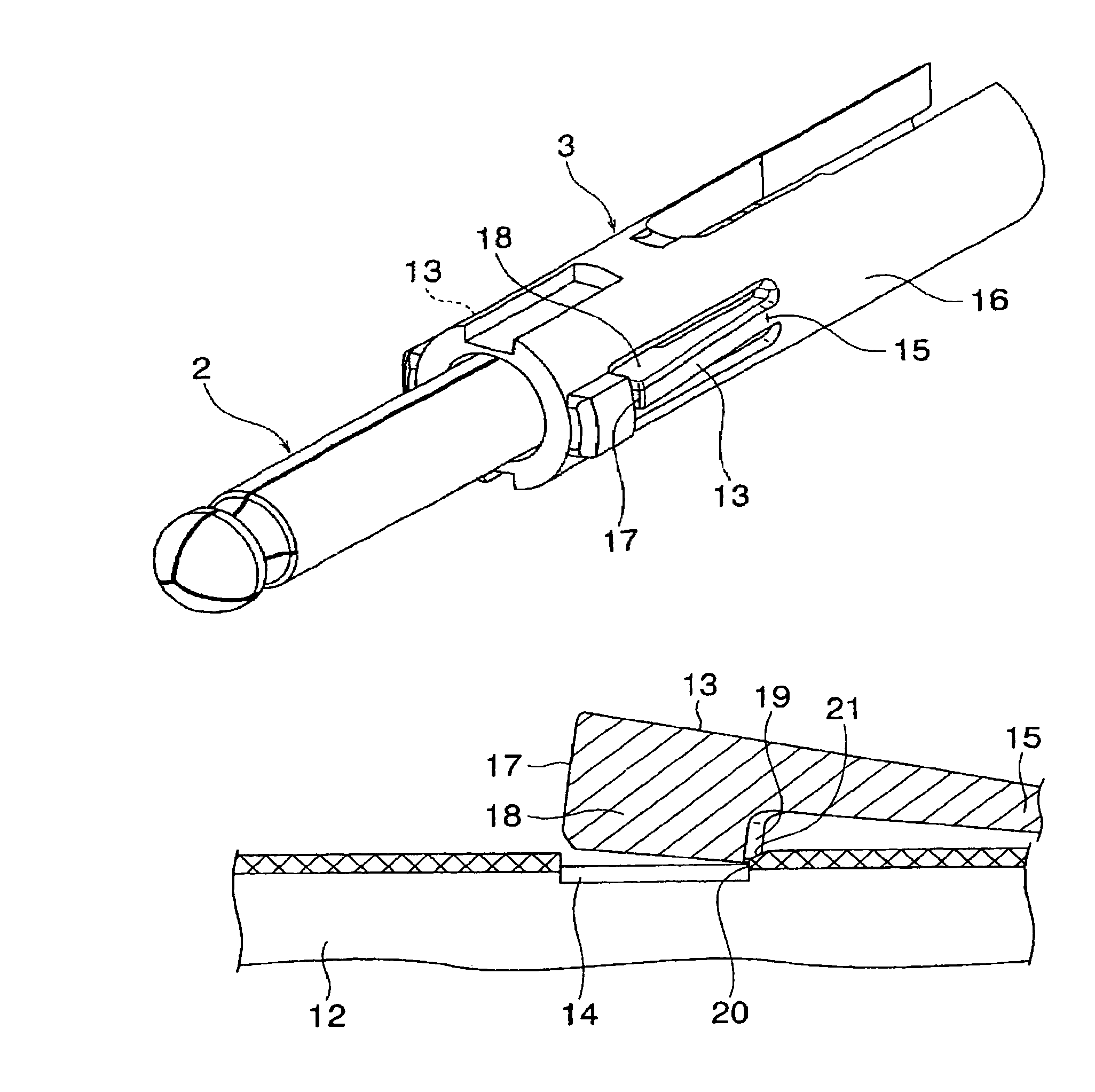
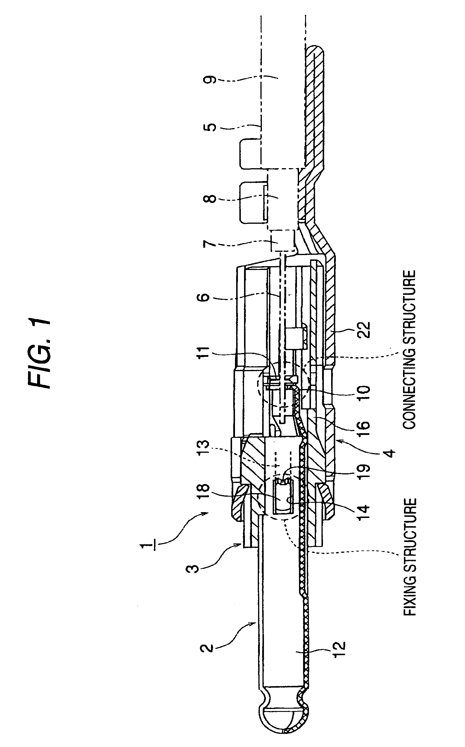
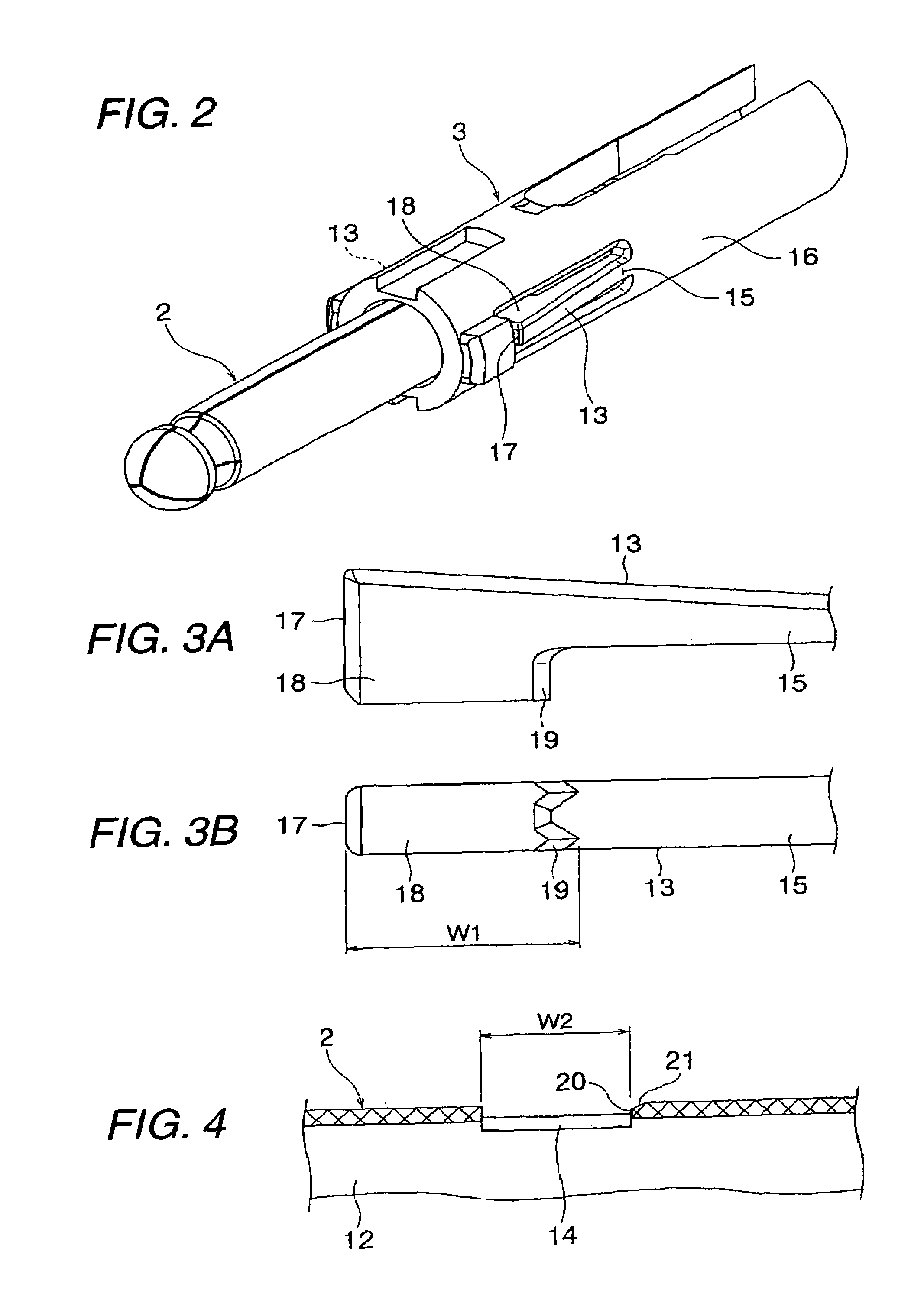
[0047]The present invention will now be described with reference to the drawings. FIG. 1 is a cross-sectional view showing one preferred embodiment of a connector of the invention. FIG. 2 is a perspective view showing a plug pin and an insulating housing, FIGS. 3A and 3B are views showing a retaining beam having a retaining claw, FIG. 4 is a cross-sectional view showing a retaining hole, FIG. 5 is a cross-sectional view showing a condition just before the retaining claw is inserted into the retaining hole, and FIG. 6 is a cross-sectional view showing a condition in which the retaining claw is retainingly engaged in the retaining hole.

[0048]In FIG. 1, reference numeral 1 denotes the connector of the invention used for example as an automotive antenna plug. The connector 1 of the invention includes the electrically-conductive plug pin 2 functioning as a center contact, the insulating housing 3 of an insulative nature fixed to an outer side of the plug pin 2, and an electrically-conduc...


PUM


Abstract

A connector includes an electrically conductive plug provided with a retaining hole, and an insulating housing that has a retaining member shaped in a cantilever beam. The retaining member has a retaining claw portion. The retaining claw portion has a projecting portion formed at a proximal end side of the retaining member. The projecting portion is crashed by an edge portion of the retaining hole when the retaining claw portion is engaged with the retaining hole.

Description

BACKGROUND OF THE INVENTION[0001]This invention relates to a connector (for example, an antenna plug for an automobile) including an electrically-conductive plug pin functioning as a center contact, an insulating housing of an insulative nature fixed to an outer side of the plug pin, and an electrically-conductive outer contact fixed to an outer side of the insulating housing.[0002]A related connector is disclosed in JP-A-2004-200019. In FIGS. 8 and 9, the connector 101, used for example as an automotive antenna plug, comprises an electrically-conductive plug pin 102 functioning as a center contact, an insulating housing 103 of an insulative nature fixed to an outer side of the plug pin 102, and an electrically-conductive outer contact 104 fixed to an outer side of the insulating housing 103. The connector 101 is designed to be electrically connected to an end portion of a coaxial cable 105.[0003]The coaxial cable 105 comprises a center conductor 106 serving as a core wire, an insul...

Claims


Application Information

Patent Timeline
Patent Type & Authority Patents(United States)
IPC IPC(8): H01R24/04
CPCH01R24/58H01R2103/00
Inventor ABE, KIMIHIROIKUMI, TOHRUKIMURA, SYUJI
Owner YAZAKI CORP
Why Eureka
Try Eureka