Integrated fuse with regions of different doping within the fuse neck

Inactive Publication Date: 2007-06-05
AVAGO TECH INT SALES PTE LTD
View PDF8 Cites 16 Cited by
  • Summary
  • Abstract
  • Description
  • Claims
  • Application Information

AI Technical Summary

Benefits of technology

[0012]Further advantages of integrated fuses according to the present invention can include an improved post fuse resistance distribution and an increased minimum resistance value in the post fuse r

Problems solved by technology

In addition, as CMOS device sizes decrease, it is increasingly difficult to blow a polysilicon

Method used


Image

  • Integrated fuse with regions of different doping within the fuse neck
  • Integrated fuse with regions of different doping within the fuse neck
  • Integrated fuse with regions of different doping within the fuse neck

Examples


Embodiment Construction

Overview

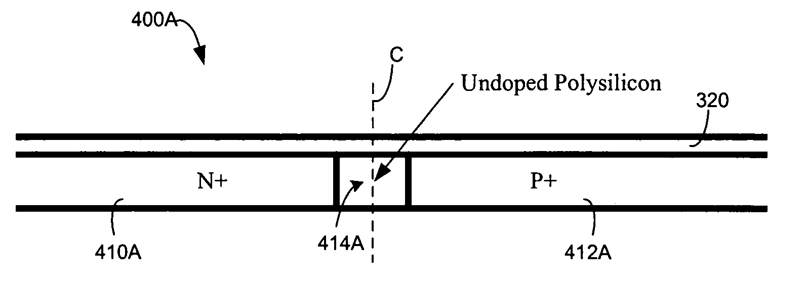
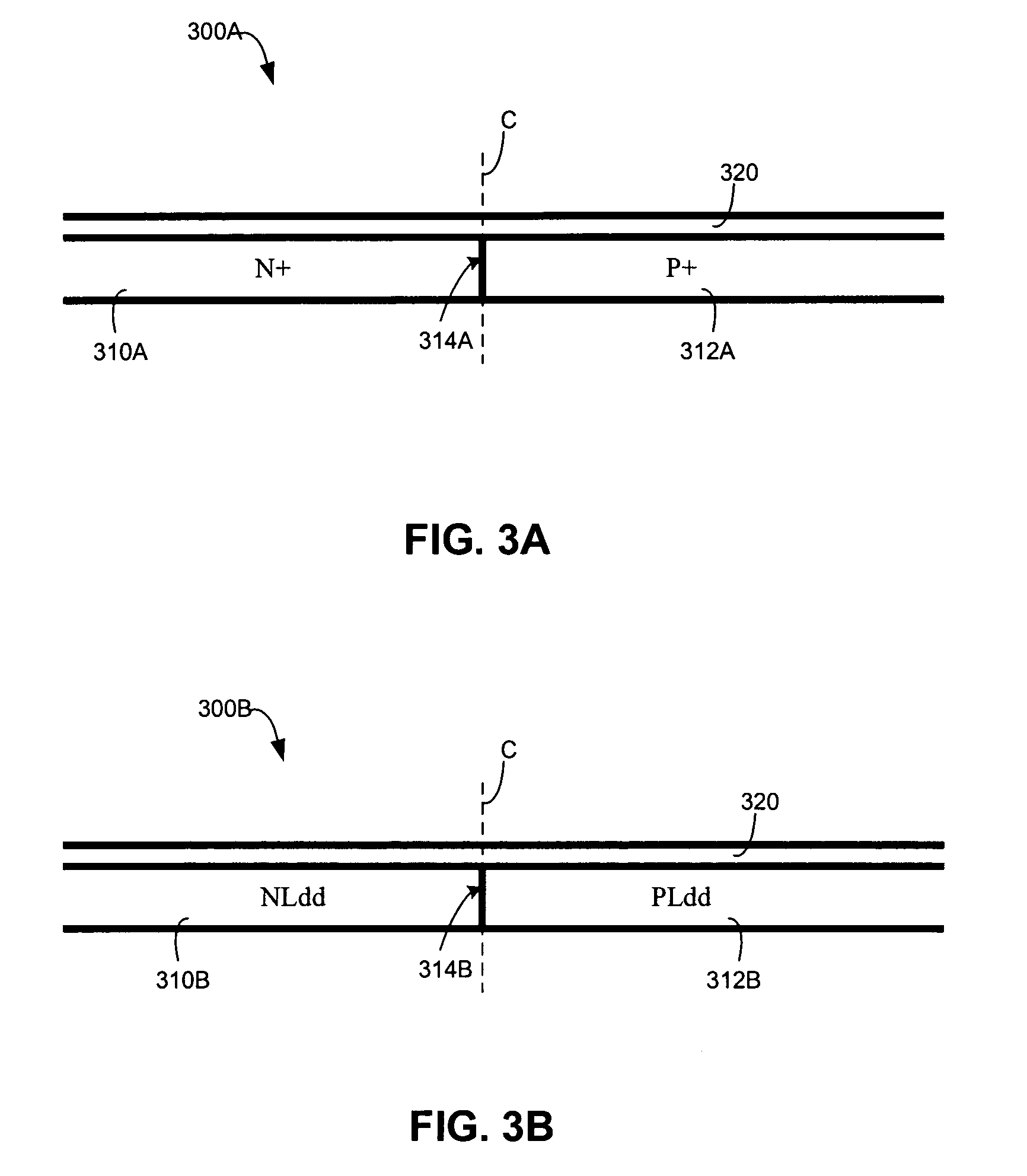
[0030]The present invention provides an integrated fuse with regions of different doping located within a fuse neck. During a fusing event, a distribution of temperature peaks occur around the regions of different dopants. By locating regions of different dopants within the fuse neck, agglomeration starts reliably and efficiently within the fuse neck (for example, at or near the center of the fuse neck) and proceeds toward the contact regions. Further advantages of integrated fuses according to the present invention can include an improved post fuse resistance distribution and an increased minimum resistance value in the post fuse resistance distribution compared to conventional polysilicon fuses.

[0031]Integrated fuses of the present invention can be used in variety of applications including, but not limited to, fuses, programmable elements, programmable read only memory (PROM), static random access memory (SRAM), redundancy implementation in logic devices, die identificatio...


PUM


Abstract

An integrated fuse has regions of different doping located within a fuse neck. The integrated fuse includes a polysilicon layer and a silicide layer. The polysilicon layer includes first and second regions having different types of dopants. In one example, the first region has an N-type dopant and the second region has a P-type dopant. The polysilicon layer can also include a third region in between the first and second regions, which also has a different dopant. During a fusing event, a distribution of temperature peaks around the regions of different dopants. By locating regions of different dopants within the fuse neck, agglomeration of the silicide layer starts reliably within the fuse neck (for example, at or near the center of the fuse neck) and proceeds toward the contact regions. An improved post fuse resistance distribution and an increased minimum resistance value in the post fuse resistance distribution is realized compared to conventional polysilicon fuses.

Description

CROSS-REFERENCE TO RELATED APPLICATIONS[0001]This application is a continuation of U.S. Non-Provisional application entitled “An Integrated Fuse With Regions of Different Doping Within The Fuse Neck,” Ser. No. 10 / 409,584, filed Apr. 9, 2003 now U.S. Pat. No. 6,770,948 which is a continuation of U.S. Non-Provisional application entitled “An Integrated Fuse With Regions of Different Doping Within The Fuse Neck,” Ser. No. 10 / 115,013, filed Apr. 4, 2002, now U.S. Pat. No. 6,580,156 all of which are incorporated by reference herein in its entirety.BACKGROUND OF THE INVENTION[0002]1. Field of the Invention[0003]The present invention relates to semiconductor devices and methods. In particular, the present invention relates to integrated fuses.[0004]2. Background Art[0005]Integrated fuses, such as polysilicon fuses, are used as programmable elements in a variety of applications. An integrated fuse can be programmed or set to an open or closed state. The open and closed states are also refer...

Claims


Application Information

Patent Timeline
IPC IPC(8): H01L29/00G11C17/16H01L21/768H01L21/82H01L23/525H01L23/58
CPCH01L23/5256Y10S257/91H01L2924/0002H01L2924/00
Inventor ITO, AKIRACHEN, HENRY K.
Owner AVAGO TECH INT SALES PTE LTD
Why Eureka
Try Eureka