
Piezoelectric device with amplifying mechanism

a technology of piezoelectric devices and amplifying mechanisms, applied in piezoelectric/electrostrictive/magnetostrictive devices, piezoelectric/electrostriction/magnetostriction machines, electrical apparatus, etc., can solve the problems of large force, high cost, and easy damage of actuators,

Active Publication Date: 2007-06-05
ASM ASSEMBLY AUTOMATION LTD
View PDF3 Cites 8 Cited by
  • Summary
  • Abstract
  • Description
  • Claims
  • Application Information

AI Technical Summary

Benefits of technology

"The invention is an improved piezoelectric device that solves some of the problems of previous devices. It includes a mechanical amplifier, two flexible platforms, and piezoelectric material mounted on each platform. The piezoelectric material flexes the platforms, creating a displacement output or force input. The technical effect of this invention is an improved piezoelectric device that can better control the flexing of the platforms, resulting in more precise and reliable performance."

Problems solved by technology

Traditional actuation by pneumatic, hydraulic or electromagnetic means cannot fulfill modern machinery requirements in terms of response time, frequency, resolution and size.
The construction of these actuators is usually based on bulky, fragile and expensive smart material elements like piezoelectric multilayer stacks and complex and expensive mechanical amplifiers, which make these actuators vulnerable to damage and very complex and expensive.
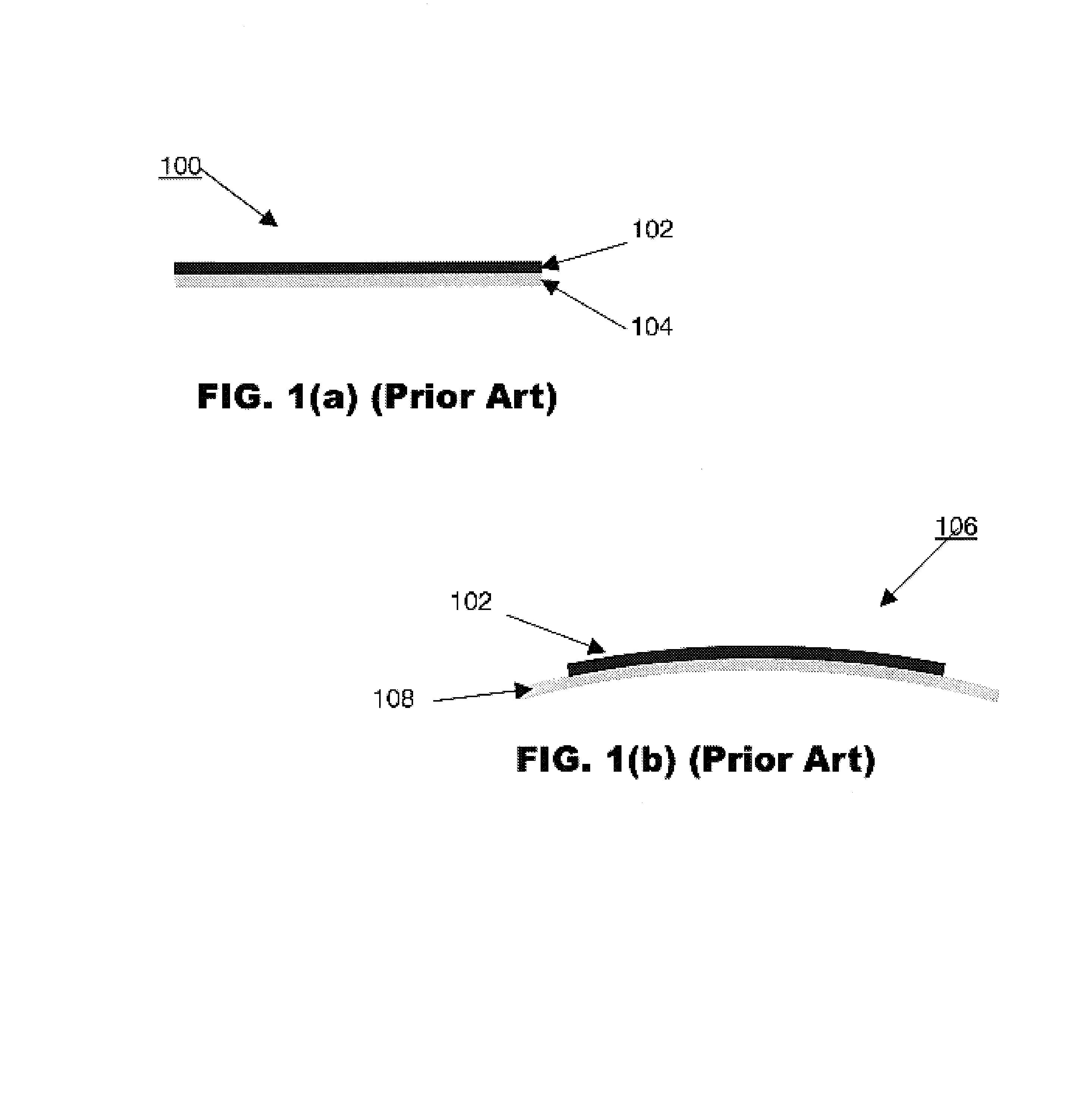
However, their blocked forces are relatively small due to their small flexural strength, and their applications are generally limited to those requiring smaller loading.
However, it has a limited loading capacity, as explained above.
Nevertheless, it is vulnerable to damage and is expensive to produce.
Although this descendent device 106 possesses better performance, it suffers from installation problems due to its inherent curvature which makes the device performance sensitive to mounting.
Reliability of the device under operation is also worsened due to the concentrated loading on the curved surface of the device, which induces stress concentration and rubbing on the brittle piezoelectric ceramic layers.

Method used


Image

  • Piezoelectric device with amplifying mechanism
  • Piezoelectric device with amplifying mechanism
  • Piezoelectric device with amplifying mechanism

Examples


Embodiment Construction

[0023]Various embodiments of piezoelectric devices according to the present invention are hereinafter described with reference to the drawings. However, the invention is not limited to such embodiments illustrated in the drawings.

[0024]In the following description, the term “piezoelectric materials” refers to those materials that can change their shapes in response to an electrical signal and can respond to an applied load by producing an electrical signal. These piezoelectric materials are preferably but not exclusively piezoelectric ceramics, such as lead zirconate titanate (PZT), barium titanate (BaTiO3), lead magnesium niobate-lead titanate (PMN-PT) and lead zirconate niobate-lead titanate (PZN-PT).

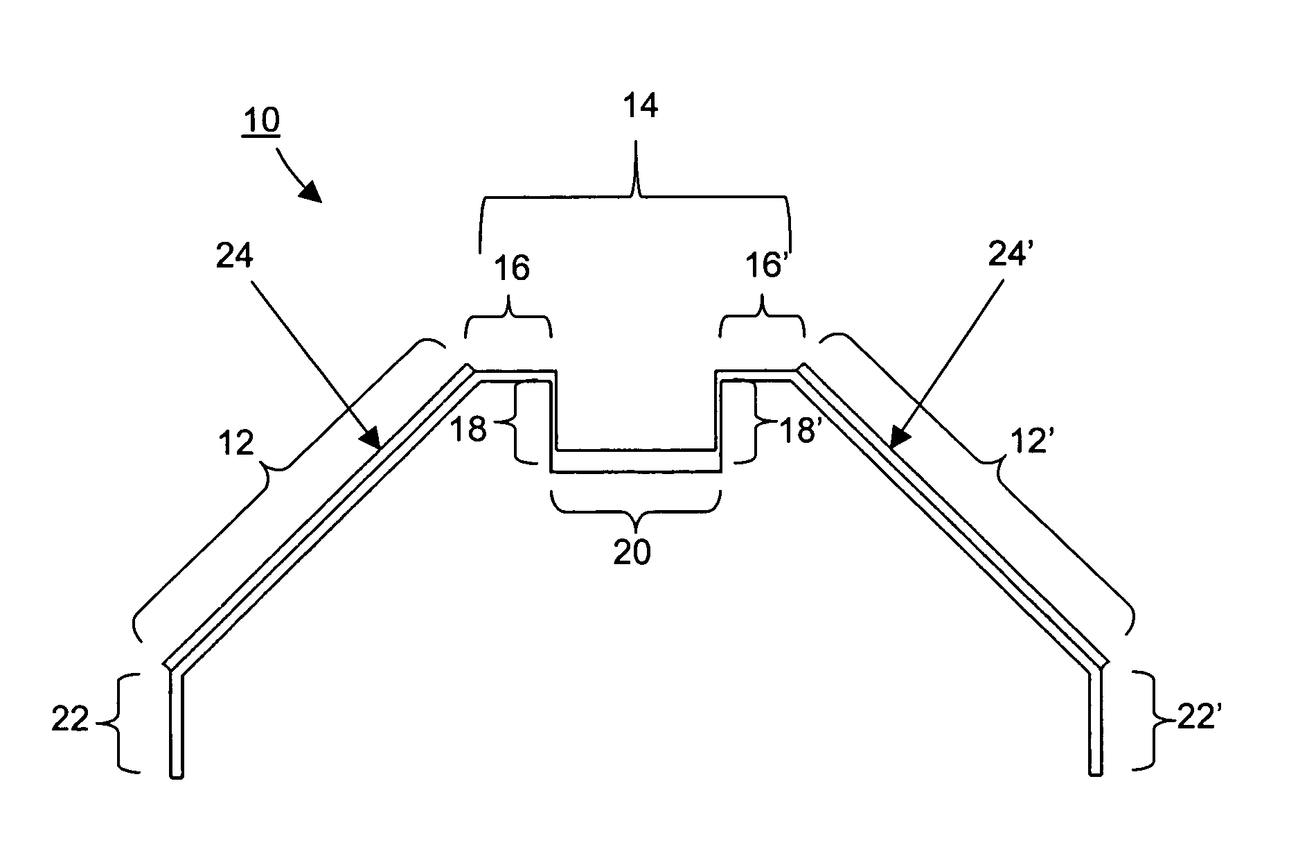
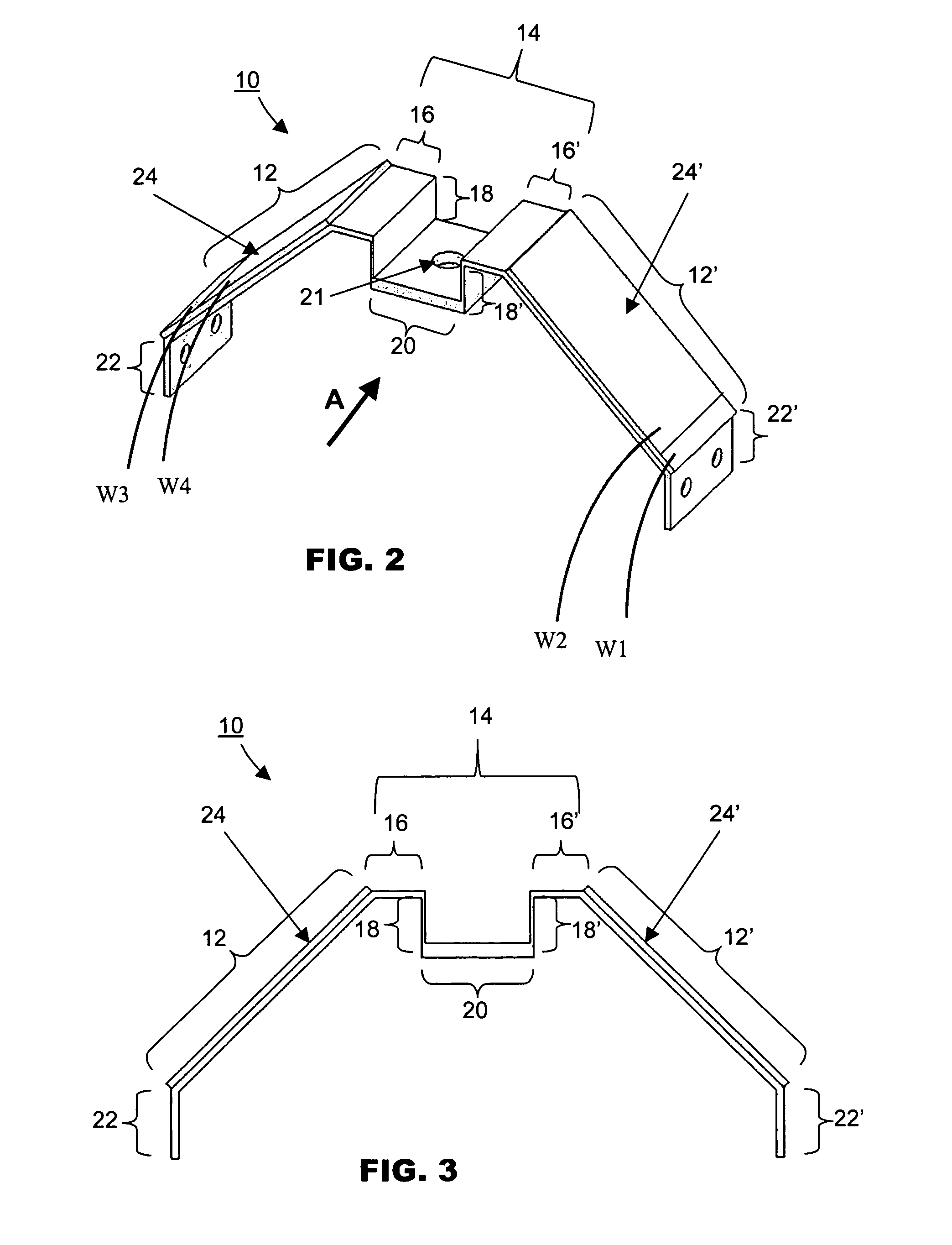
[0025]FIG. 2 is an isometric view of a piezoelectric device 10 according to a first preferred embodiment of the present invention. The piezoelectric device 10 is constructed with a mechanical amplifier in the form of a saddle-like amplifying structure 14 and driving parts comprising a...


PUM


Abstract

A piezoelectric device is provided that comprises a mechanical amplifier adapted to produce a displacement output and / or receive a force input, and first and second flexible platforms connected to the mechanical amplifier. The first flexible platform is connected to one side of the mechanical amplifier and piezoelectric material is mounted on the first flexible platform for controllably flexing the first flexible platform. The second flexible platform is connected to another side of the mechanical amplifier and piezoelectric material is mounted to the second flexible platform for controllably flexing the second flexible platform.

Description

FIELD OF THE INVENTION[0001]The invention relates to piezoelectric devices, and in particular to piezoelectric devices having structures that include mechanical amplifiers. The piezoelectric devices are suitable for use in a variety of applications, such as for actuation, force sensing and / or sensoriactuation.BACKGROUND AND PRIOR ART[0002]Actuators are extensively used in mechanical, electronic and optical systems like positioning lenses in telescopes, focusing in microscopes or vibration suppression in dedicated equipment. Traditional actuation by pneumatic, hydraulic or electromagnetic means cannot fulfill modern machinery requirements in terms of response time, frequency, resolution and size. Thus, several classes of actuators using piezoelectric, magnetostrictive and shape memory alloy smart materials have been developed for these applications.[0003]The construction of these actuators is usually based on bulky, fragile and expensive smart material elements like piezoelectric mul...

Claims


Application Information

Patent Timeline
Patent Type & Authority Patents(United States)
IPC IPC(8): H01L41/08H10N30/00
CPCH01L41/0946H02N2/028H02N2/043H10N30/2043H02N2/00
Inventor OR, SIU WINGYUNG, CHUNG SHUENGCHAN-WONG, LAI WA HELENCHOY, PING KONG JOSEPHLIU, CHOU KEE PETER
Owner ASM ASSEMBLY AUTOMATION LTD
Learn More