
Two channel digital phase detector

a digital phase detector and two-channel technology, applied in the direction of resistance/reactance/impedence, digital variable/waveform display, instruments, etc., can solve the problem of phase noise measurement being limited to approximately 150 db/hz below the carrier frequency, and the output signal from averaging substantially below the noise level of a single system, so as to achieve low phase noise measurement

Inactive Publication Date: 2007-06-05
TIMING SOLUTIONS CORP
View PDF17 Cites 24 Cited by
  • Summary
  • Abstract
  • Description
  • Claims
  • Application Information

AI Technical Summary

Benefits of technology

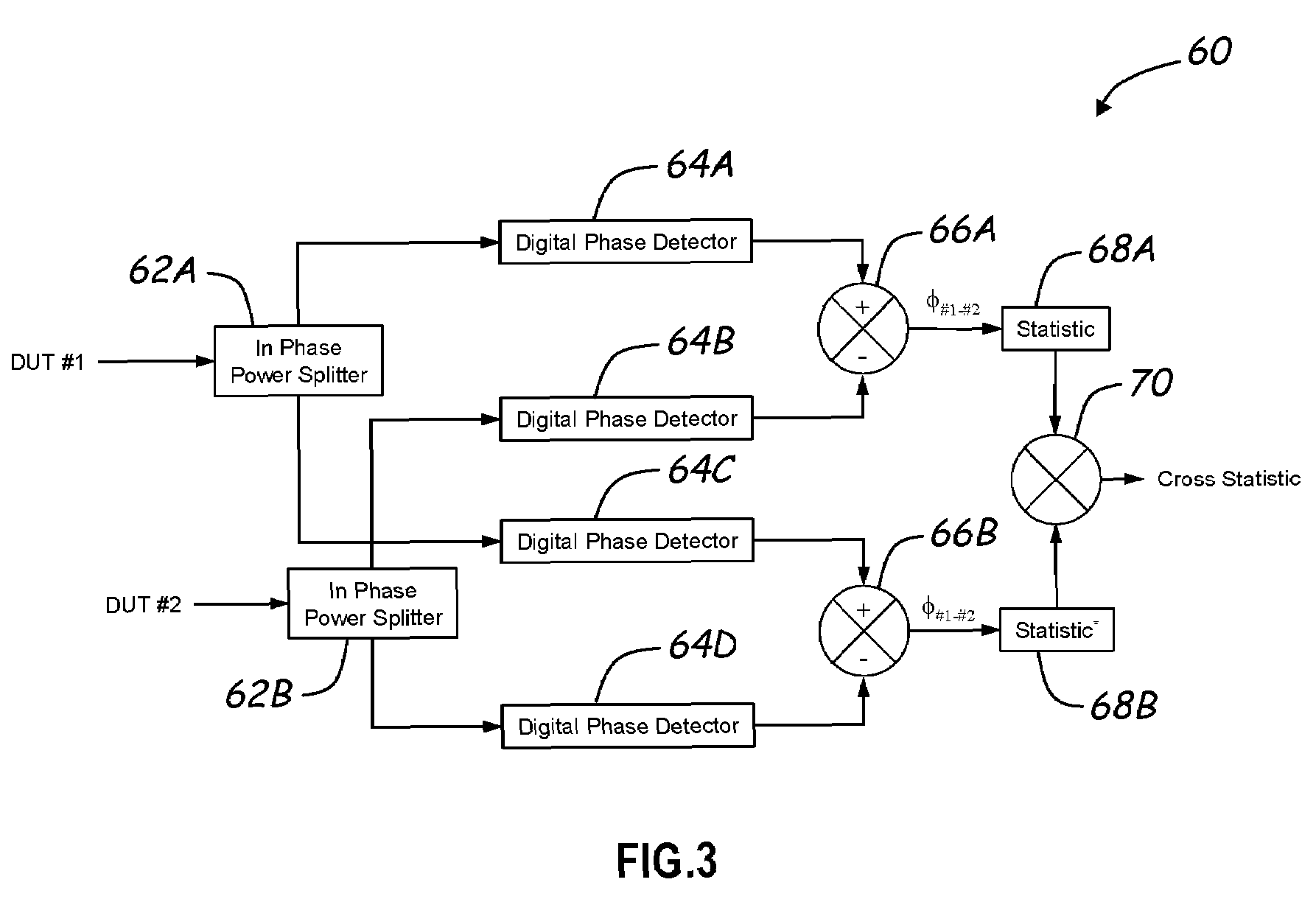
[0005]The present invention is directed to a digital phase detector that is capable of being used in a phase measurement system to make very low phase noise measurements and, in one embodiment, as low as about 180 dB / Hz below the carrier frequency. In this regard, analysis of efforts to utilize the prior digital phase detector approach to make very low phase noise measurements revealed the source of the limitation. Specifically, in an effort to use the prior digital phase detector approach to make such measurements, the signals from two DUTs were each applied to a prior digital phase detector. The outputs from the two prior digital phase detectors were then subtracted from one another and processed to determine the phase noise. Two identical phase measurement systems were used to estimate the cross phase noise spectrum in order to resolve DUT noise below the noise floor of the individual digital phase detectors. However, it was determined that the phase noise measurements were limited to approximately 150 dB / Hz below the carrier frequency in all but a very limited case. It was recognized that the reason for the limited applicability of the prior digital phase detector approach in making phase noise measurements beyond about 150 dB / Hz below the carrier frequency was attributable to the signal of one of the two DUTs being in phase or close to being in phase with the sampling clock when the other was near quadrature. During this period of time, the sampling clock's broadband noise has a substantially different effect on the samples of the signal associated with one DUT than it has on the samples of the signal associated with the other DUT. As a consequence, the signal output by one of the prior digital phase detectors and indicative of the phase difference between one DUT and the sample clock had different sampling clock noise than the output of the other prior digital phase detector. When two independent but similar measurements systems, such as the noted two prior digital phase detectors, are used to compute the cross phase noise spectrum, the impressed sampling clock noise associated with both systems prevents the results or output signals from averaging substantially below the noise level of a single system.

Problems solved by technology

In this regard, analysis of efforts to utilize the prior digital phase detector approach to make very low phase noise measurements revealed the source of the limitation.
However, it was determined that the phase noise measurements were limited to approximately 150 dB / Hz below the carrier frequency in all but a very limited case.
When two independent but similar measurements systems, such as the noted two prior digital phase detectors, are used to compute the cross phase noise spectrum, the impressed sampling clock noise associated with both systems prevents the results or output signals from averaging substantially below the noise level of a single system.

Method used


Image

  • Two channel digital phase detector
  • Two channel digital phase detector
  • Two channel digital phase detector

Examples


Embodiment Construction

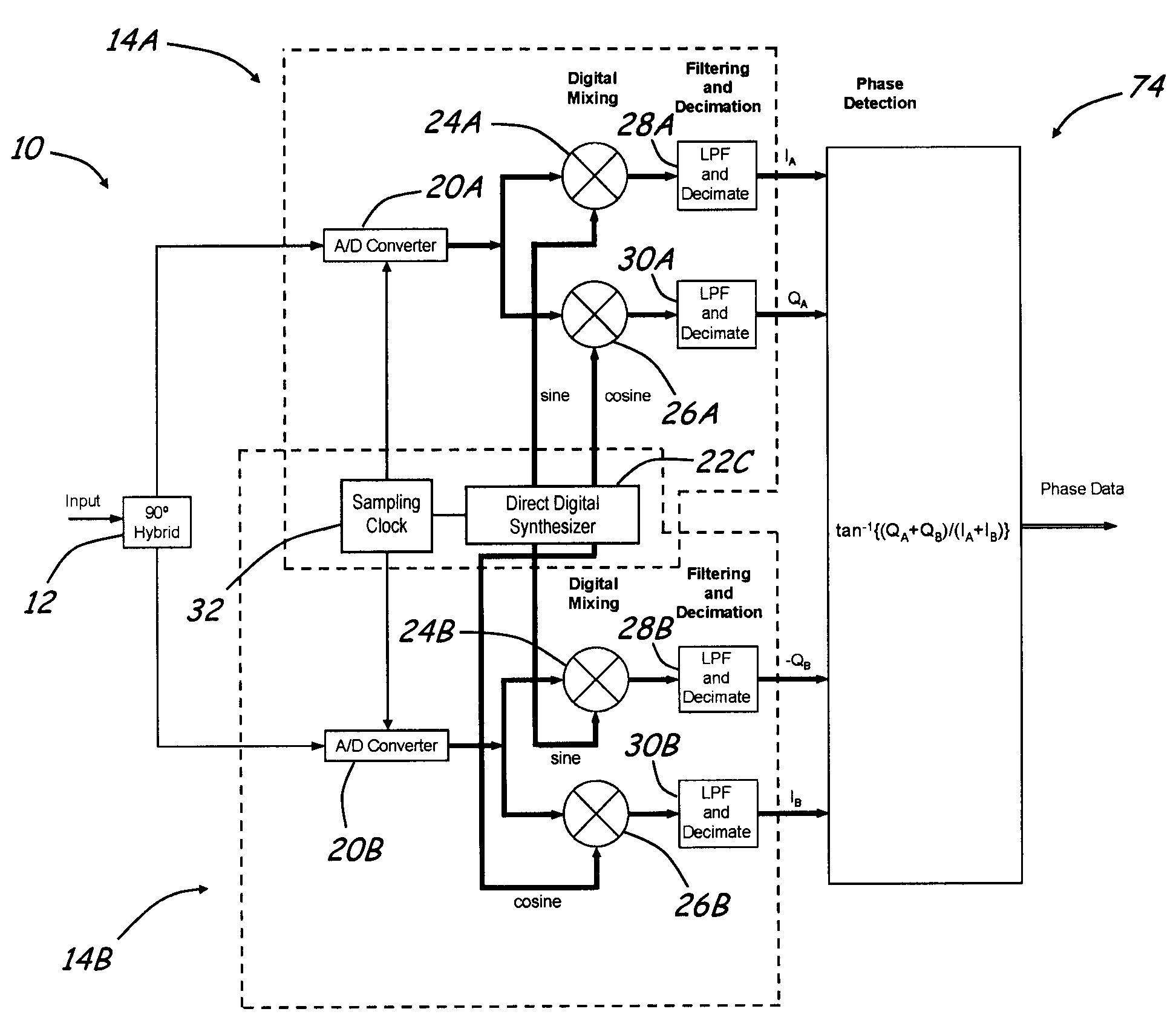
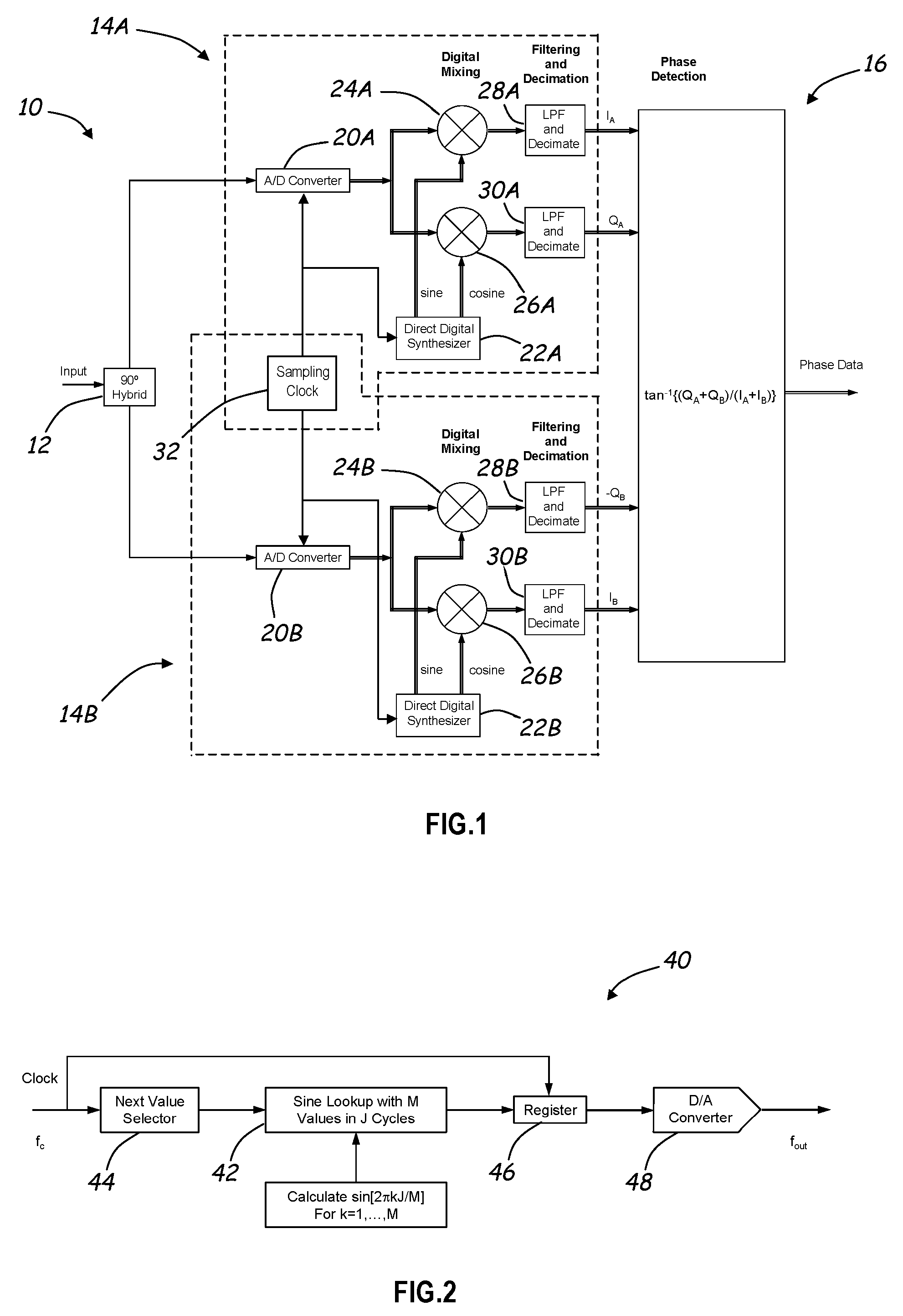
[0013]With reference to FIG. 1, an embodiment of a digital phase detector 10 according to the invention is described. Generally, the digital phase detector 10 is comprised of: (a) a signal splitter and phase shifter 12 for receiving an input signal, the phase of which is to be measured relative to a reference signal, and providing a first signal that is substantially identical to the input signal and second signal that is phase shifted by desired amount relative to the first signal; (b) a first analog-to-digital channel 14A for processing the first signal to produce a first in-phase signal and a first quadrature signal; (c) a second analog-to-digital channel 14B for processing the second signal to produce a second in-phase signal and a second quadrature signal; and (d) a phase detector 16 for processing the first and second in-phase signals and the first and second quadrature signals to produce a phase difference signal that is representative of the difference in phase between the s...


PUM


Abstract

The invention is directed to a digital phase detector that comprises a splitter and phase shifter to receive a signal of a device under test and produce a first signal that is substantially identical to the received signal and a second signal that is phase shifted relative to the first signal. A first analog-to-digital channel processes the first signal to produce an in-phase and quadrature signals. The second signal is processed by a second analog-to-digital channel to produce a second set of in-phase and quadrature signals. The two sets of in-phase and quadrature signals are used to determine a phase difference between the signal of the device under test and a local oscillator signal associated with the two analog-to-digital channels. The invention is further directed to a direct digital synthesizer that is capable of use within the digital phase detector and in other applications. The direct digital synthesizer comprises a sine look-up table or calculator that provides a digital signal representative of the amplitude of a sine wave at an angle of 2πkJ / M where J is an integer number of cycles of the sine wave, M is an integer number of sine wave data values that represent J cycles of the sine wave, and k is an integer number having a value in a range extending from 1 to and including M. By appropriately selecting the value of M, certain spur related issues can be avoided. Further, appropriate selection of J and M allows the synthesizer to generate frequencies that are rational fractions of the frequency of a clock applied to the synthesizer.

Description

FIELD OF THE INVENTION[0001]The present invention relates to a digital phase detector for use in determining the phase difference between the signal produced by a device under test (“DUT”) and a reference oscillator.BACKGROUND OF THE INVENTION[0002]Many applications require precision clocks or oscillators, which are hereinafter collectively referred to as oscillators. For example, many radar systems require precision oscillators that exhibit phase noise that is as much as 180 dB / Hz below the carrier frequency. Consequently, before an oscillator can be integrated into such a system, the oscillator must be tested to determine if oscillator meets the phase noise requirements of the system.[0003]Presently, there is an analog technique that is capable of measuring phase differences that are as much as 180 dB / Hz below the carrier or reference signal. The analog technique involves applying the signal of a DUT and a local oscillator signal to a mixer. The mixer operates to produce an interm...

Claims


Application Information

Patent Timeline
Patent Type & Authority Patents(United States)
IPC IPC(8): G01R25/00G01R13/02G01R27/02H04B1/00
CPCG01R25/005H03D13/004
Inventor SOLBRIG, WAYNE E.
Owner TIMING SOLUTIONS CORP
Learn More