Antenna adaptation comparison method for high mobility

a technology of directional antenna and high mobility, applied in the direction of polarisation/directional diversity, transmission monitoring, baseband system details, etc., can solve the problems of loss of signal strength between the field unit and the base station, problem may be more noticeable, and the gain provided by the directional antenna is quickly reduced, so as to minimize the effect of signal degradation and improve the performance of the field unit equipped

Inactive Publication Date: 2007-06-05
IPR LICENSING INC
View PDF8 Cites 11 Cited by
  • Summary
  • Abstract
  • Description
  • Claims
  • Application Information

AI Technical Summary

Benefits of technology

[0010]To improve performance of field units equipped with directional antennas in a rapidly changing environment, it would be advantageous if a re-scan (i.e., selection of a new scan angle) could occur during non-idle times and at a high enough rate to minimize signal degradation effects caused by the rapidly changing environment (e.g., the user's spinning).

Problems solved by technology

A problem with taking measurements for selecting scan angles during idle times occurs when the field unit employing a directional antenna is used in a vehicle traveling at a relatively high rate of speed.
In such a case, the “best” scan angle changes while the field unit is “in use,” thereby causing loss of signal strength between the field unit and base station.
The problem may be more noticeable in the case of a field unit, such as a cellular telephone equipped with a directional antenna, being used by an individual who simply “spins” with the phone, such as at a rate of 60 degrees per second.
In this case, the gain provided by the directional antenna quickly diminishes due to pointing error, and signal degradation or drop-out may be experienced by the field unit.

Method used


Image

  • Antenna adaptation comparison method for high mobility
  • Antenna adaptation comparison method for high mobility
  • Antenna adaptation comparison method for high mobility

Examples


Embodiment Construction

[0026]A description of preferred embodiments of the invention follows. A description of preferred embodiments of the invention follows.

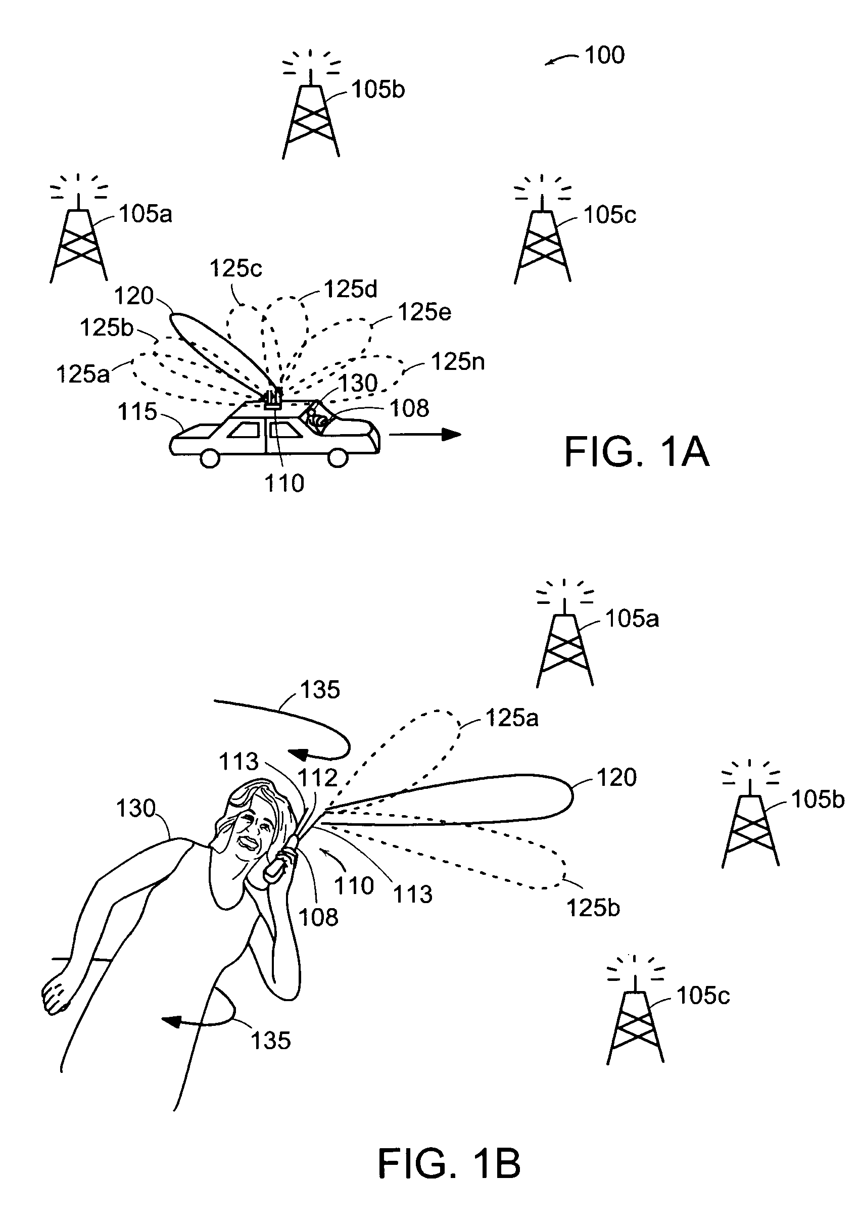
[0027]FIG. 1 is a diagram of a wireless communications network 100 in which the present invention may be employed. The network 100 may be a Code Division Multiple Access (CDMA), Time Division Multiple Access (TDMA), Time Division Duplex (TDD), Frequency Division Duplex (FDD), WiFi, Wireless Local Area Network (WLAN), or other wireless network. The network 100 includes base stations 105a, 105b, 105c (collectively 105) and wireless communications field unit 108 having a directional antenna 110, such as described in U.S. Pat. No. 6,515,635 by Chiang et al. issued Feb. 4, 2003 or U.S. patent application Ser. No. 09 / 859,001 by Gothard et al., filed May 16, 2001 entitled “Adaptive Antenna for Use in Wireless Communication System,” and technique for optimizing the use of the directional antenna 110, such as described in U.S. patent application Ser. No. 09 / 7...


PUM


Abstract

A system causes a scan angle of a directional antenna to change temporarily from a current scan angle to at least one trial scan angle during reception of predetermined portions of an information carrying signal. At the trial scan angle(s), a trial metric associated with each trial scan angle is determined by the system. The system then selects a next scan angle based on the trial metrics. Examples of predetermined portions of the information carrying signal include the Power Control Bit (PCB) and certain symbol periods of the Forward Error Correction (FEC) block.

Description

RELATED APPLICATION(S)[0001]This application claims the benefit of U.S. Provisional Application No. 60 / 363,669, filed on Mar. 11, 2002 and U.S. Provisional Application No. 60 / 363,214, filed Mar. 8, 2002; the entire teachings of the above application(s) are incorporated herein by reference.BACKGROUND OF THE INVENTION[0002]Code Division Multiple Access (CDMA) communication systems may be used to provide wireless communications between a base station and one or more field units. The base station is typically a computer controlled set of transceivers that are interconnected to a land-based public switched telephone network (PSTN). The base station includes an antenna apparatus for sending forward link radio frequency signals to the field units. The base station antenna is also responsible for receiving reverse link radio frequency signals transmitted from each field unit.[0003]Each field unit also contains an antenna apparatus for the reception of the forward link signals and for transm...

Claims


Application Information

Patent Timeline
Patent Type & Authority Patents(United States)
IPC IPC(8): H04K1/02H04L25/03H04L25/49H04B7/10H01Q1/24H01Q3/44H01Q19/32H04B7/26H04W16/28
CPCH01Q3/44H01Q19/32H04W16/28H04B17/00H01Q1/24
Inventor PROCTOR, JR., JAMES A.AMALFITANO, CARLORYU, KIL H.
Owner IPR LICENSING INC
Why Eureka
Try Eureka