Optical waveguide lens and method of fabrication

a technology of optical waveguides and fabrication methods, applied in the field of optical waveguide lenses, can solve the problems of difficult manufacturing and high cost of commercially available grin lenses

Inactive Publication Date: 2007-06-05
CORNING INC
View PDF29 Cites 41 Cited by
  • Summary
  • Abstract
  • Description
  • Claims
  • Application Information

AI Technical Summary

Benefits of technology

[0014]A further aspect of the present invention is a method for fabricating an optical waveguide lens comprising the steps of providing an optical waveguide, providing a lens blank defining a cross-sectional dimension substantially greater than the diameter of the optical waveguide, fusing the lens blank to the optical waveguide, heating a portion of the lens blank above its softening point, applying tension to the lens blank until it separates to form a segment having a tapered distal end connected to the optical waveguide, and heating the tapered distal end of the lens blank above its softening point such that a spherical lens portion is formed in alignment with the axis of the optical waveguide and through which the light beam is transmitted, the optical waveguide lens defining a throat portion disposed between the optical waveguide and the spherical lens portion whose cross-sectional dimension is substantially greater than the diameter of the optical waveguide and substantially less than the diameter of the spherical lens portion.

Problems solved by technology

However, commercially-available GRIN lenses are expensive, difficult to manufacture, and present certain disadvantages in assembling, aligning, and tuning the optical components.

Method used


Image

  • Optical waveguide lens and method of fabrication
  • Optical waveguide lens and method of fabrication
  • Optical waveguide lens and method of fabrication

Examples


Embodiment Construction

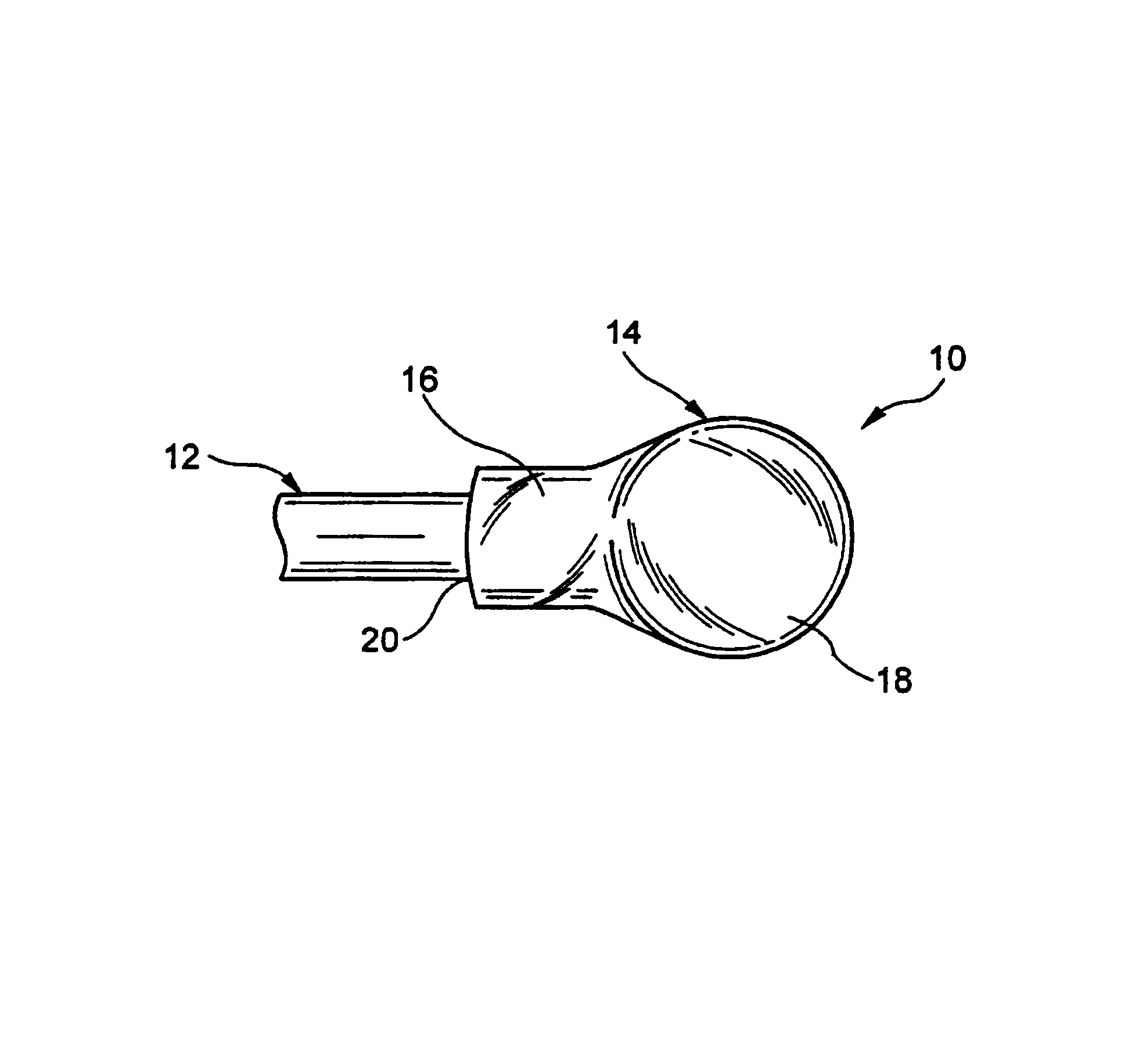
[0043]Reference will now be made in detail to the present preferred embodiments of the invention, examples of which are illustrated in the accompanying drawings. Wherever possible, the same reference numbers will be used throughout the drawings to refer to the same or like parts. An exemplary embodiment of the optical waveguide lens of the present invention is shown in FIG. 1, and is designated generally throughout by reference numeral 10.

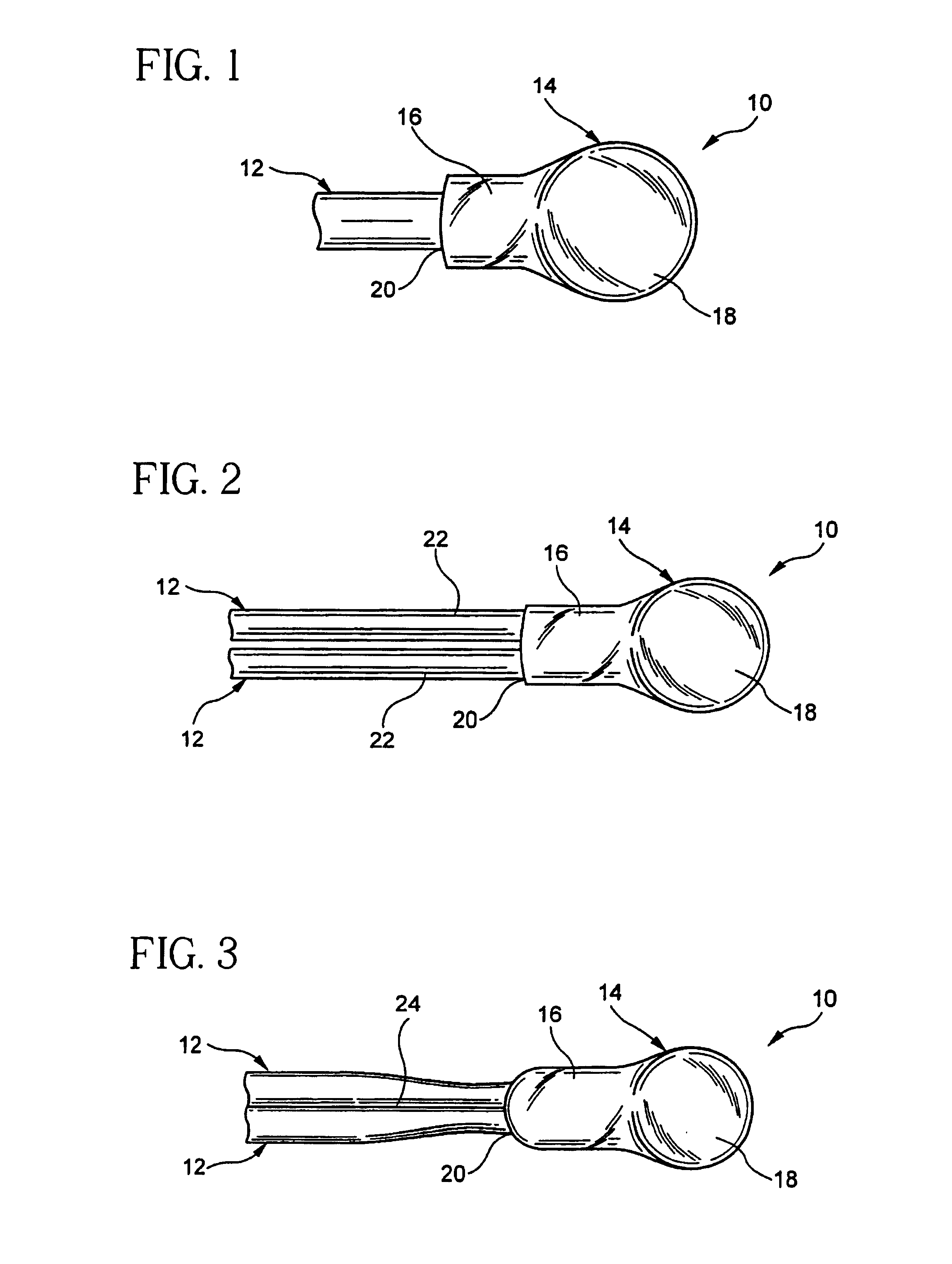
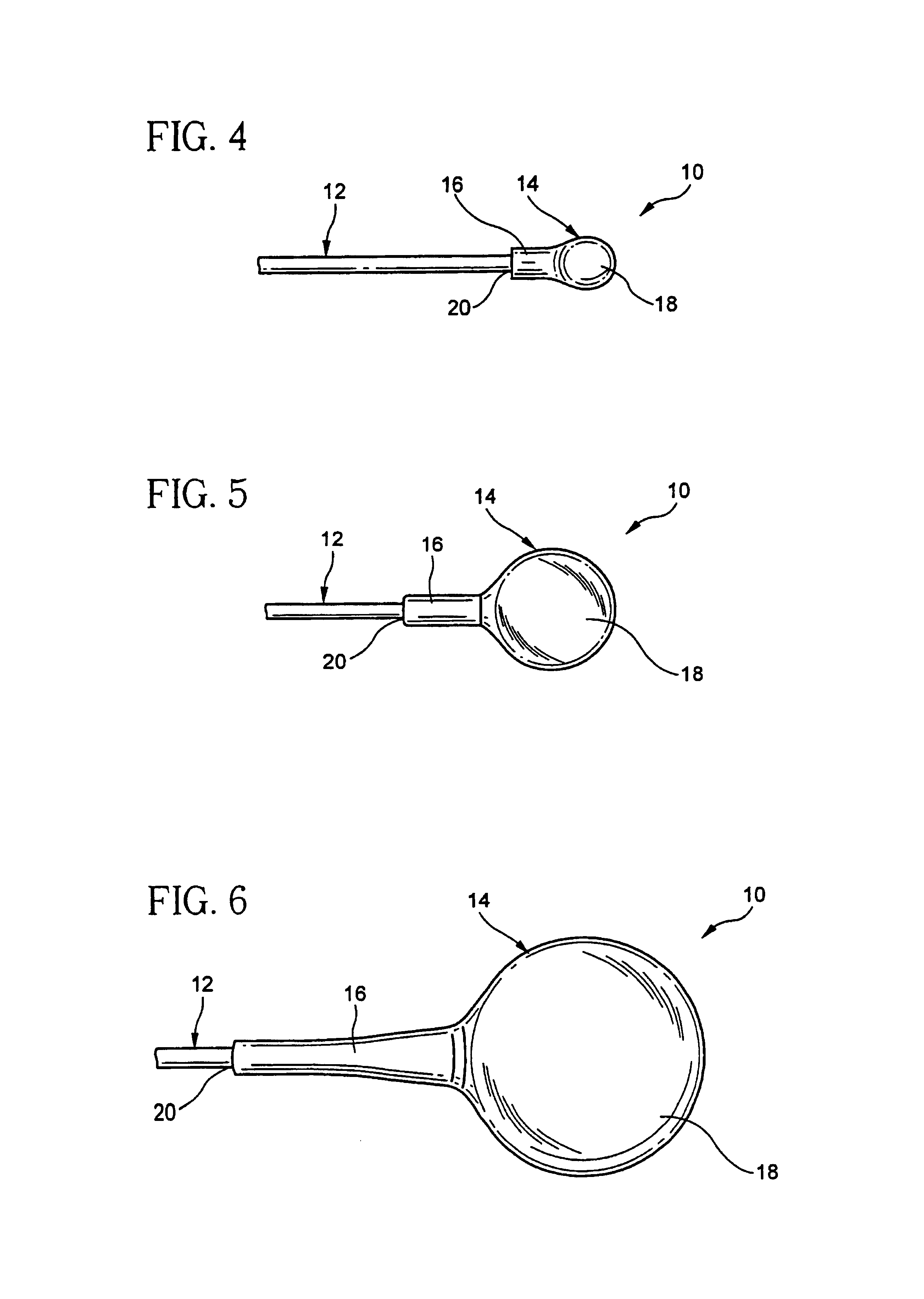
[0044]In accordance with the invention, referring to FIGS. 1-6 it may be seen that the present invention for an optical waveguide lens 10 includes an optical waveguide 12, a lens member 14 having a throat portion 16 and a generally spherical lens portion 18. The lens member 14 is attached to the optical waveguide 12 at a junction 20 formed by fusion splicing the lens member 14 to the optical waveguide 12 according to the process described further below.

[0045]FIG. 1 depicts an optical waveguide lens 10 in which a conventional optical waveguide 12 (s...


PUM


Abstract

A spherical lens formed by fusing a generally homogenous glass lens blank to the distal end of an optical fiber, heating and tensioning the lens blank to separate it in two segments with the segment attached to the optical fiber defining a tapered end, and heating the lens blank above its softening point so that the spherical lens forms. The lens blank is fabricated from a 4 weight percent borosilicate glass having a softening point less than that of the core of the optical fiber. The lens member defines a throat region adjacent the optical fiber whose cross-sectional dimension is substantially greater than the diameter of the optical fiber, but substantially less than the diameter of the spherical lens.

Description

[0001]This application claims the benefits of Provisional application No. 60 / 190,200 filed Mar. 17, 2000.BACKGROUND OF THE INVENTION[0002]1. Field of the Invention[0003]The present invention relates generally to optical waveguide lenses used for collimating or focusing a light beam traversing free space in an optical component, and particularly to a spherical lens formed on the distal end of an optical fiber.[0004]2. Technical Background[0005]Advances in optical communications have generated significant need for optical components which involve light being transmitted to or from an optical fiber through free-space to interact with or pass through one or more optical device. A wide variety of passive and active optical devices exist, some simple examples including thin-film filters or birefringent elements, and some of the more complex being large scale three-dimensional switch fabrics. Other uses for free-space optical components include injecting light from a laser diode into an op...

Claims


Application Information

Patent Timeline
Patent Type & Authority Patents(United States)
IPC IPC(8): G02B6/32G02B3/00G02B6/02G02B6/255G02B6/26G02B6/293G02B6/34
CPCG02B6/2552G02B6/262G02B6/32
Inventor BHAGAVATULA, VENKATA A.HIMMELREICH, JOHNWILLIAMS, GREGORY E.UKRAINCZYK, LJERKAWAGNER, ROBERT S.
Owner CORNING INC
Why Eureka
Try Eureka