Bulk material precision transfer chute apparatus

a technology of precision transfer chute and bulk material, which is applied in the direction of conveyor parts, loading/unloading, packaging, etc., can solve the problems of increasing the cost of operating the conveyor, disadvantaged in several respects of the conventional bulk material transfer chute described above, and material turbulence, so as to prevent material puddles and minimize material spillage

Active Publication Date: 2007-06-12
BENETECH INC
View PDF8 Cites 15 Cited by
  • Summary
  • Abstract
  • Description
  • Claims
  • Application Information

AI Technical Summary

Benefits of technology

[0014]The bulk material precision transfer chute apparatus of the present invention overcomes the disadvantages associated with prior art transfer chutes discussed above by providing an adjustable and novel transfer and loading chute construction that transfers bulk material from a discharge conveyor to a receiving conveyor while controlling the material velocity and profile, avoiding material degradation, reducing the generation of dust, reducing accumulation of material within the chute, and reducing wear to the transfer chute and receiving conveyor. The transfer chute of the invention also eliminates the need for a loading skirt, thereby reducing the transfer chute manufacturing costs, maintenance costs, safety and health risks, and energy consumption. The chute construction provides the benefits of vertical adjustments of the chute flow path to best suit it for the condition of the coal (i.e. wet or dry). Wet coal could be dropped more vertically to prevent build-up and to adjust the velocity of discharge to the receiving conveyor. Horizontal adjustment also allows for center loading of the receiving conveyor. The adjustability avoids plugging of the chute.

Problems solved by technology

The turbulence is created in the material by the uncontrolled flow of the material through the chute and the change in the material velocity when the faster moving material impacts with the slower moving receiving conveyor.
Additionally, the constant pressure of the contact of the seals against the receiving conveyor on both sides of the conveyor system creates a frictional drag on the receiving conveyor that requires increasing the horsepower of the receiving conveyor motive source, thus increasing the cost of operating the conveyor.
The conventional bulk material transfer chute described above is disadvantaged in several respects.
The bulk material discharged from the discharge conveyor that impacts with the transfer chute at the top of the chute interior creates dust, reduces the size of the material deposited into the chute, and causes wear to the wall of the chute that is impacted by the material.
The impact of the material with the interior wall surfaces and corners causes a continuous build-up of material and can cause plugging of the chute.
The plugging stops the flow of material through the chute and increases safety risks due to the potential for fire or an explosion, and increases maintenance costs to clear the plug.
In some chute transition and loading section designs, the freefall of the bulk material through the chute and onto the surface of the receiving conveyor can cause wear to the conveyor and can generate dust or spillage.
The random flow of the material through the chute can cause off center loading of the material on the surface of the receiving conveyor.
This often results in spillage of the material from the sides of the receiving conveyor which increases maintenance costs for maintaining the skirting, and presents a safety and health hazard due to dust generation which could be inhaled by persons or could create a fire or explosion hazard.
The need for the loading skirt at the output of the chute transition section also adds to maintenance costs and increases the overall cost and health and safety risks of the transfer chute.
The skirt drags on the conveyor causing wear to the conveyor and skirt, and increases power requirements of the conveyor.
While DEM has proved to be successful in many applications, this method of chute design also has distinct disadvantages.
In a power plant application, frequently material particle size changes due to altering suppliers of coal and often due to associated equipment performance such as coal crushers and granulators.
Environmental conditions such as high moisture content due to heavy rain and freezing conditions, adversely affect the coefficient of friction between the bulk material particles and the boundary surfaces of the chute interior.
This change in the coefficient of friction as a result of varying environment conditions renders the DEM inefficient in controlling material velocity.

Method used


Image

  • Bulk material precision transfer chute apparatus
  • Bulk material precision transfer chute apparatus
  • Bulk material precision transfer chute apparatus

Examples


Embodiment Construction

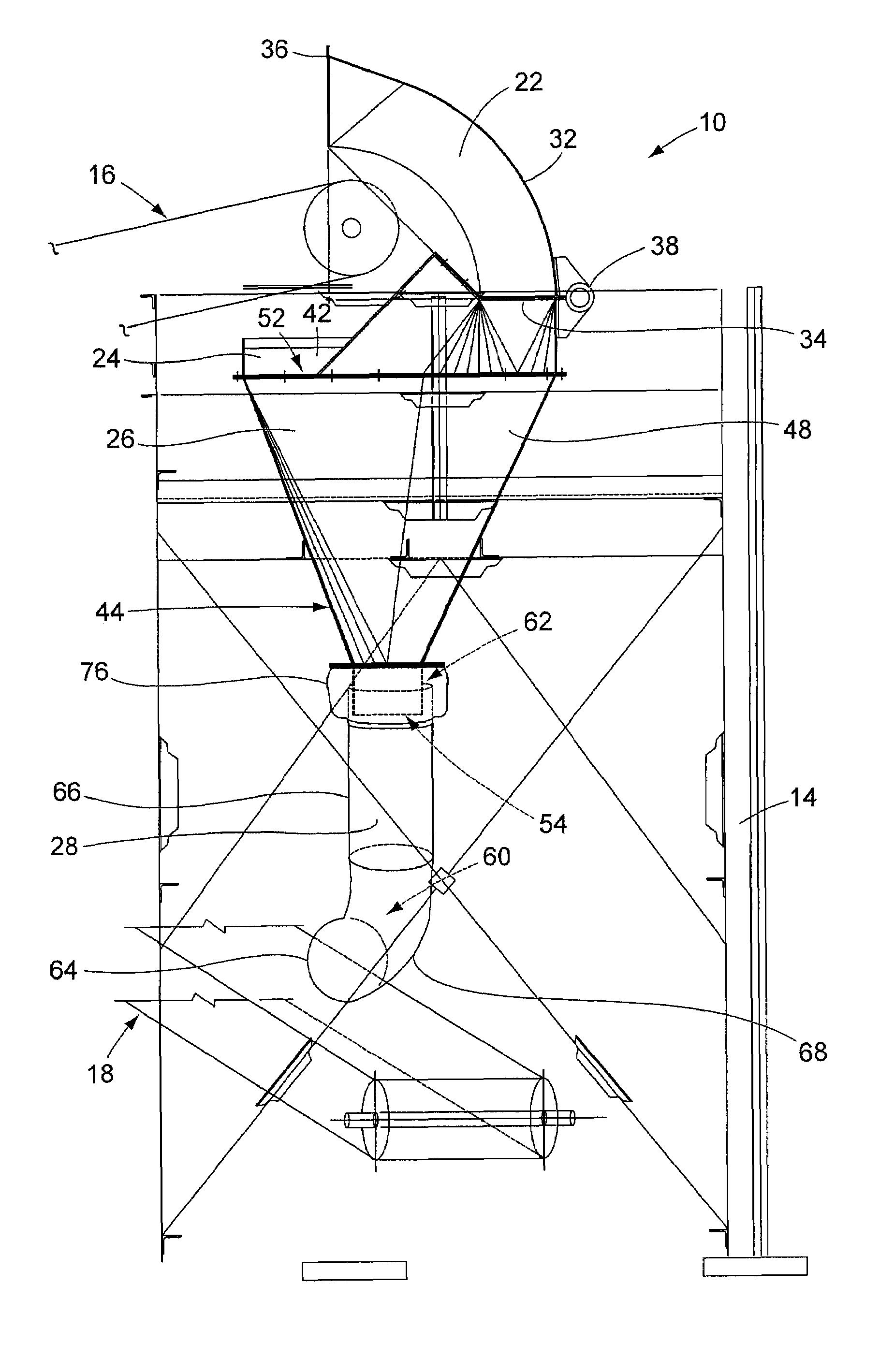
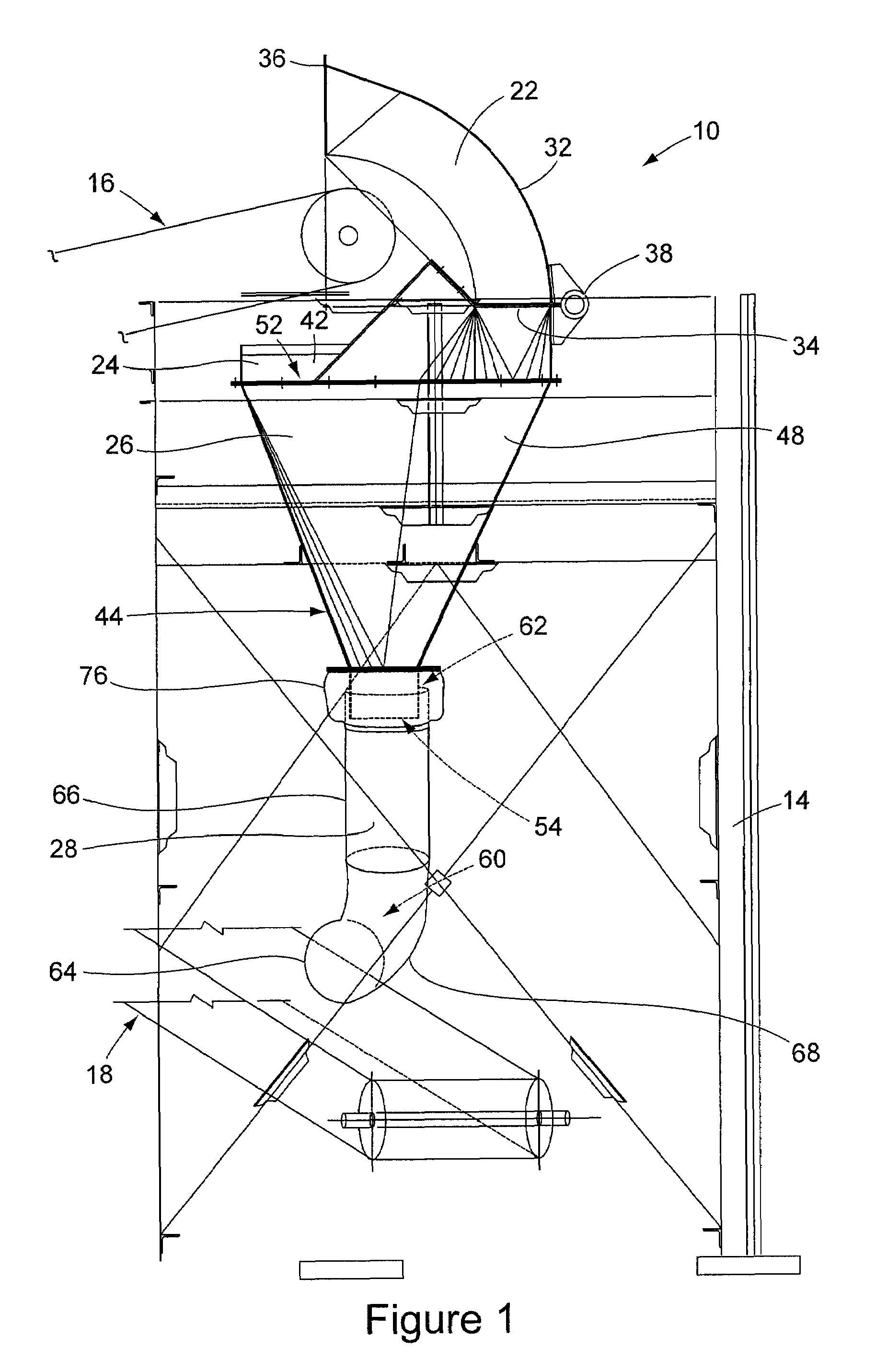
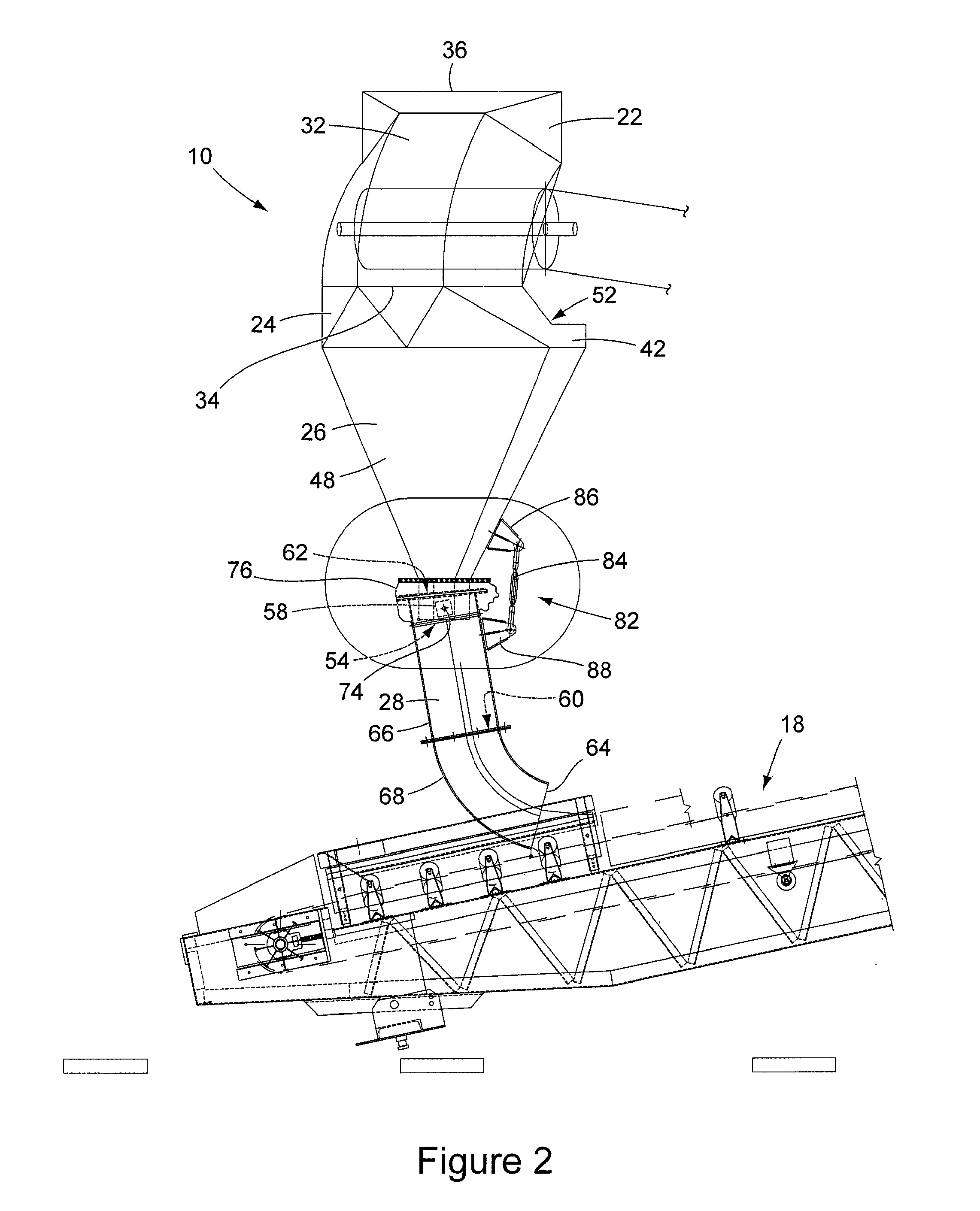
[0033]FIGS. 1 and 2 show an embodiment of the bulk material precision transfer chute apparatus 10 of the present invention. The apparatus 10 is shown in FIG. 1 supported by a schematically represented framework 14 between the discharge end of a discharge conveyor 16 and the receiving end of a receiving conveyor 18. In the illustrative environment of the apparatus 10 shown in FIGS. 1, 2, and 3, the apparatus is used to transfer bulk material, for example coal, from the discharge conveyor 16 positioned above the apparatus to the receiving conveyor 18 positioned below the apparatus. It should be understood that the environment shown in FIGS. 1, 2, and 3 is illustrative only, and should not be interpreted as limiting. As shown in FIGS. 1 and 2, the bulk material transfer apparatus 10 of the invention is basically comprised of a hood 22 positioned at the top of the apparatus, a transition section 26 positioned below the hood 22, and a loading tube 28 positioned below the transition secti...


PUM


Abstract

A bulk material precision transfer chute apparatus transfers a flow of material from a discharge conveyor to a separate receiving conveyor. The apparatus receives a flow of material from the discharge conveyor and transfers that material to a receiving conveyor depositing the material in a precise manner that avoids spillage of the material from the receiving conveyor, avoids wear to the receiving conveyor, and avoids excess dust generation from the transfer of the material.

Description

BACKGROUND OF THE INVENTION [0001](1) Field of the Invention[0002]The present invention pertains to a bulk material transfer chute that transfers a flow of material from a discharge conveyor to a separate receiving conveyor. In particular, the present invention pertains to a precision transfer chute that receives a flow of material from a discharge conveyor and transfers that material to a receiving conveyor and deposits the flow of material onto the surface of the receiving conveyor in a precise manner that avoids spillage of the material, avoids excess dust generation from the transfer of the material, reduces material degradation, reduces stress and wear of the receiving conveyor components thereby reducing maintenance and repair costs, and reduces the power requirements of the receiving conveyor.[0003](2) Description of the Related Art[0004]The transporting of bulk material, for example coal, from one area to another often involves the transfer of a stream or flow of the materia...

Claims


Application Information

Patent Timeline
Patent Type & Authority Patents(United States)
IPC IPC(8): B65G47/44
CPCB65G11/126B65G11/186B65G69/181B65G47/44B65G2207/48B65G11/00
Inventor PIRCON, JOHN S.WESTFALL, RONALD A.CLARK, GREGORY A.
Owner BENETECH INC
Why Eureka
Try Eureka