High sensitivity scanning probe system

a scanning probe and high sensitivity technology, applied in the field of scanning probe systems, can solve the problems of optical interference, limited vertical resolution, and inability to provide the vertical resolution of optical techniques, and achieve the effect of cancelling out noise in the scanning probe system

Inactive Publication Date: 2007-06-12
NAT UNIV OF SINGAPORE
View PDF15 Cites 6 Cited by
  • Summary
  • Abstract
  • Description
  • Claims
  • Application Information

AI Technical Summary

Benefits of technology

[0017]According to a fourth aspect of the present invention, the interferometer comprises a first and a second mirror, wherein the first and second mirrors are mounted on a first and second actuators, respectively. The first actuator is operable to adjust the period and / or orientation of the fringe pattern of the interference beam, while the second actuator is operable to modulate the fringe pattern and cancel out noise in the scanning probe system.

Problems solved by technology

The laser light reflected off the cantilever tip enters the laser diode and interferes optically with the light reflected internally from the front face of the laser diode.
Nevertheless, for common cantilever designs, this type of sensor is Johnson noise limited (as reported by O. Hanson, et al., in Nanotechnology, vol 10, issue 51, 1999) and thus cannot provide the vertical resolution of optical techniques.
However, vertical resolution is limited by parasitic capacitances (as reported by S. A. Miller, et al., in Review of Scientific Instruments, vol 68, p 4155, 1997).
However, there exists a physical limit beyond which the optical steepness cannot be increased further.
In addition, the use of a beam with high optical steepness creates difficulty in aligning the light beam on the cantilever probe and photodetector.
In the case of array cantilever sensing, optical lever detection is limited by the need to design an array of photodetectors with each photodetector having a provision for position-adjustment to give maximum sensitivity.
However, these sensors are expensive to manufacture.
However, the divided intensity reduces optical steepness and in turn reduces the measurement sensitivity.
In addition, the manufacture of micron size features on the cantilever is expensive.
More significantly, poor production of these micron-sized features affects the quality of the diffraction pattern and hence influences measurement accuracy.
Another issue in the design of the optical cantilever sensing is noise.
Yet another issue in AFM is the mode of deflection of the cantilever.

Method used


Image

  • High sensitivity scanning probe system
  • High sensitivity scanning probe system
  • High sensitivity scanning probe system

Examples


Embodiment Construction

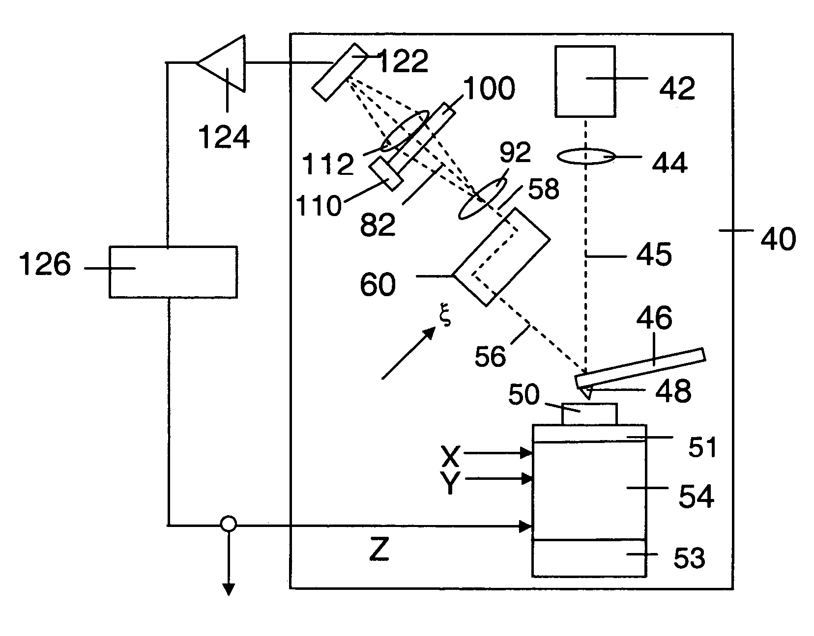
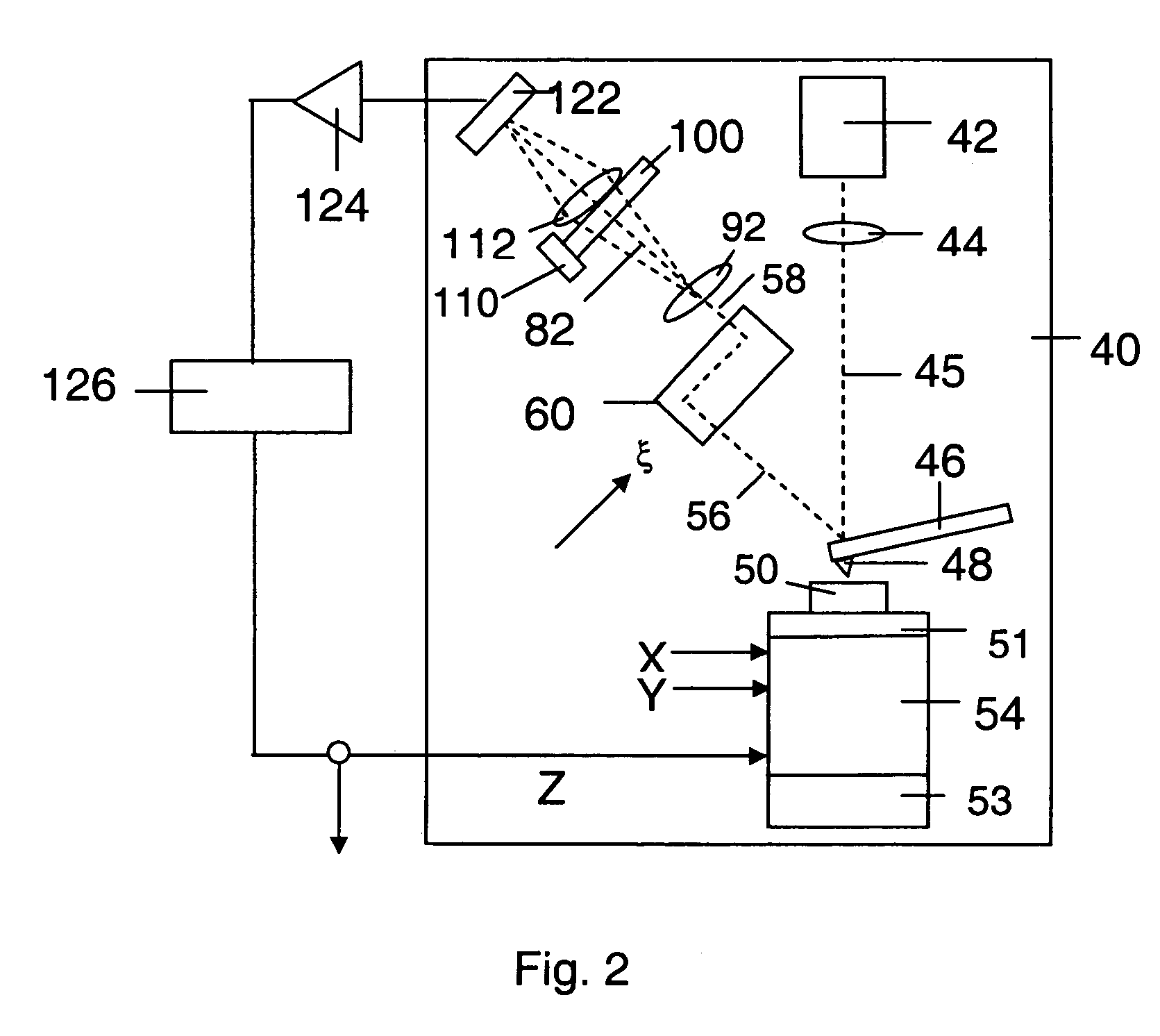
[0028]An embodiment of the present invention is shown in FIG. 2. An atomic force microscope system 40 includes a light source 42 (preferably, for example, a laser) that produces a coherent light beam 45. The light beam 45 is directed through a first lens 44 such that the light beam 45 is focused onto a cantilever probe 46, near the free-end of the probe 46. The cantilever probe 46 has a sensing tip 48 on a face opposite that on which the light beam 45 is focussed. The sensing tip 48 when in use is proximate a surface of a sample 50.

[0029]The sample 50 is mounted on a piezoelectric system 54 having a movable stage 51, movable in the X-, Y- and Z-directions within a base 53. The piezoelectric system 54 is operable to translate the sample 50 in the X-, Y- and Z-directions by applying voltages to the respective axes of a piezoelectric crystal.

[0030]The cantilever probe 46 is mounted such that the sensing tip 48 is in contact with or proximate the top surface of the sample 50. The atomic...


PUM


Abstract

The present invention provides a hybrid optical and interferometric atomic force microscope system (40) for monitoring a cantilever probe (46). A light source (42) provides a light beam which is focussed on the back of the cantilever probe (46). The light reflected off the probe is split into two beams of different path lengths and are recombined to form an interference beam (58). This interference beam (58) is passed through a grating (102) having substantially the same period and orientation as the interference beam pattern. The light transmitted through the grating (102) illuminates a photodetector (122) to give a signal according to the intensity of the light falling on the photodetector. The photodetector output signal is sent to a positioning system (126), which in turn gives a signal to the piezoelectric system (54) so that the probe (46) follows the sample (50) surface. This signal is integrated as a function of position across the scanned area to represent a characteristic of the sample surface. An array of light beams, cantilever probes and photodetectors are also provided, and a plurality of characteristics may be obtained by performing a single scan on the sample surface. Actuators are also provided on the grating (102) and mirrors in the interferometer (60, 60a, 60b) to modulate the fringes of the interference beam (58) and cancel out noise in the microscope system (40).

Description

FIELD OF INVENTION[0001]The present invention relates to a scanning probe system and in particular to a scanning probe system using optical interferometery to detect deflection of one or more probes.BACKGROUND[0002]An atomic force microscope is an instrument useful for characterising a surface at atomic resolution. A typical atomic force microscope (AFM) comprises a flexible cantilever probe with a sensing tip at one end and a photosensor to monitor the reflection of light from the free end of the cantilever probe as the probe moves over the surface of a sample.[0003]FIG. 1 shows a prior art atomic force microscope system 10. A light source 12 directs a laser beam through a lens 14. The light passing through the lens 14 is focused on a point on the cantilever 16 near the free end of the cantilever 16. The cantilever 16 has a sensing tip 18 on a face opposite that on which the light beam is focussed. The sensing tip 18 faces a surface of a sample 20.[0004]The sample 20 is mounted on ...

Claims


Application Information

Patent Timeline
Patent Type & Authority Patents(United States)
IPC IPC(8): G01B11/02G01B9/02G01Q20/02G01Q30/02G01Q60/24
CPCG01Q20/02B82Y35/00
Inventor NG, TUCK WAHCHUA, HUI TONGSASAKI, OSAMI
Owner NAT UNIV OF SINGAPORE
Why Eureka
Try Eureka