Precise x-ray inspection system utilizing multiple linear sensors

Inactive Publication Date: 2007-06-12
AGILENT TECH INC
View PDF17 Cites 8 Cited by
  • Summary
  • Abstract
  • Description
  • Claims
  • Application Information

AI Technical Summary

Benefits of technology

[0008]The use of a single x-ray source, which requires no electron beam steering or collimating due to the stationary nature of the source in relation to sensors, greatly simplifies the design of the system. Also, t

Problems solved by technology

This movement essentially causes those other layers to fade from the resulting image.
While x-ray laminography systems are exceptionally useful in many applications, such systems require rather expensive and complex technology, including the x-ray tube and drive electronics needed to implement the precise movements of an electron beam within the tube used to generate the rotating source of x-rays.
Furthermore, due to the rather small areas such systems are capable of inspecting at any one time, the number of areas and layers that are normally required to fully inspect an article are typically rather large.
As a result, such a system may require a rather protracted amount of time to perform a complete examination of each article.
However, the moving image sensor is replaced by multiple, expensive x-ray area image sensors, or in th

Method used


Image

  • Precise x-ray inspection system utilizing multiple linear sensors
  • Precise x-ray inspection system utilizing multiple linear sensors
  • Precise x-ray inspection system utilizing multiple linear sensors

Examples


Example

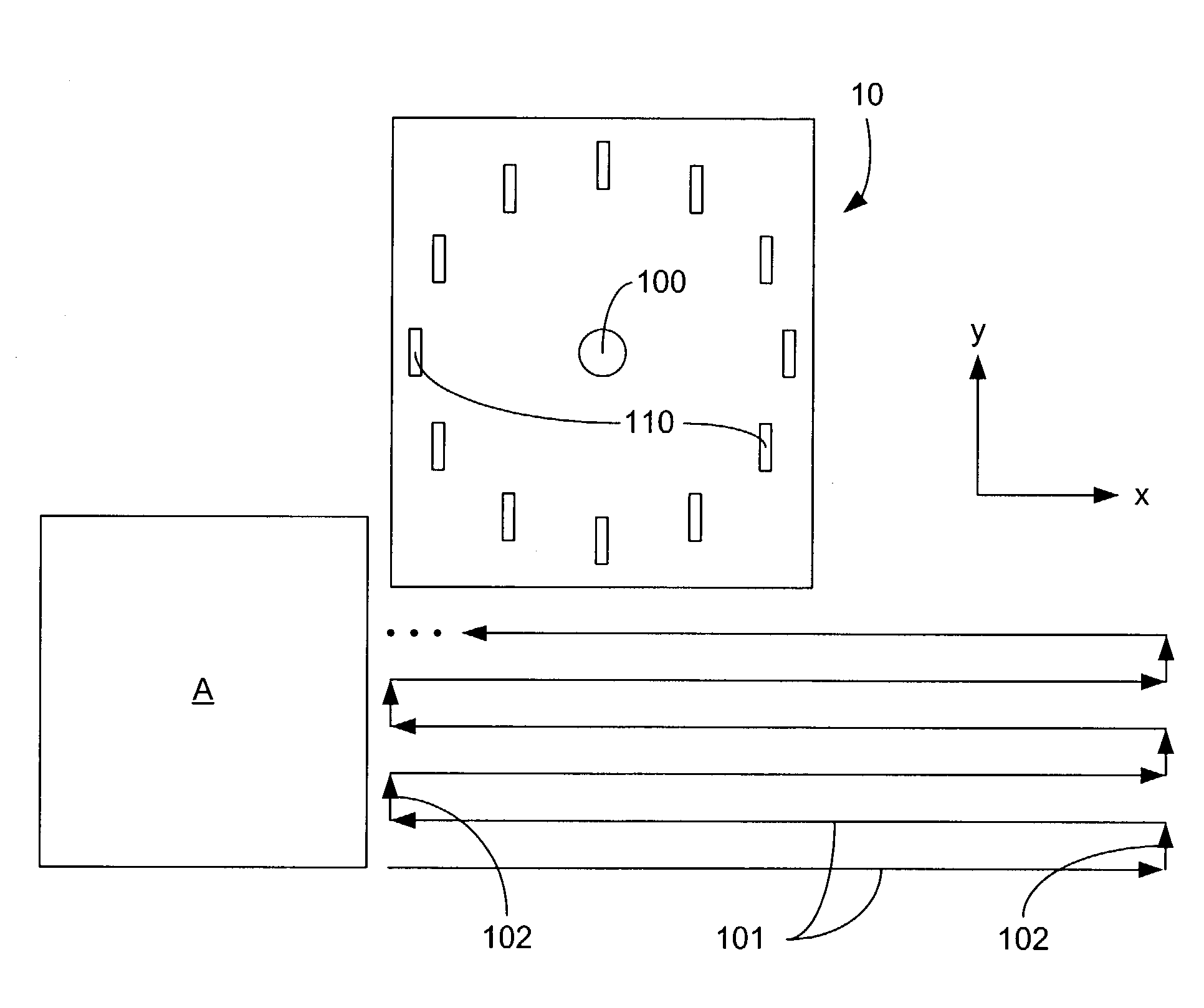
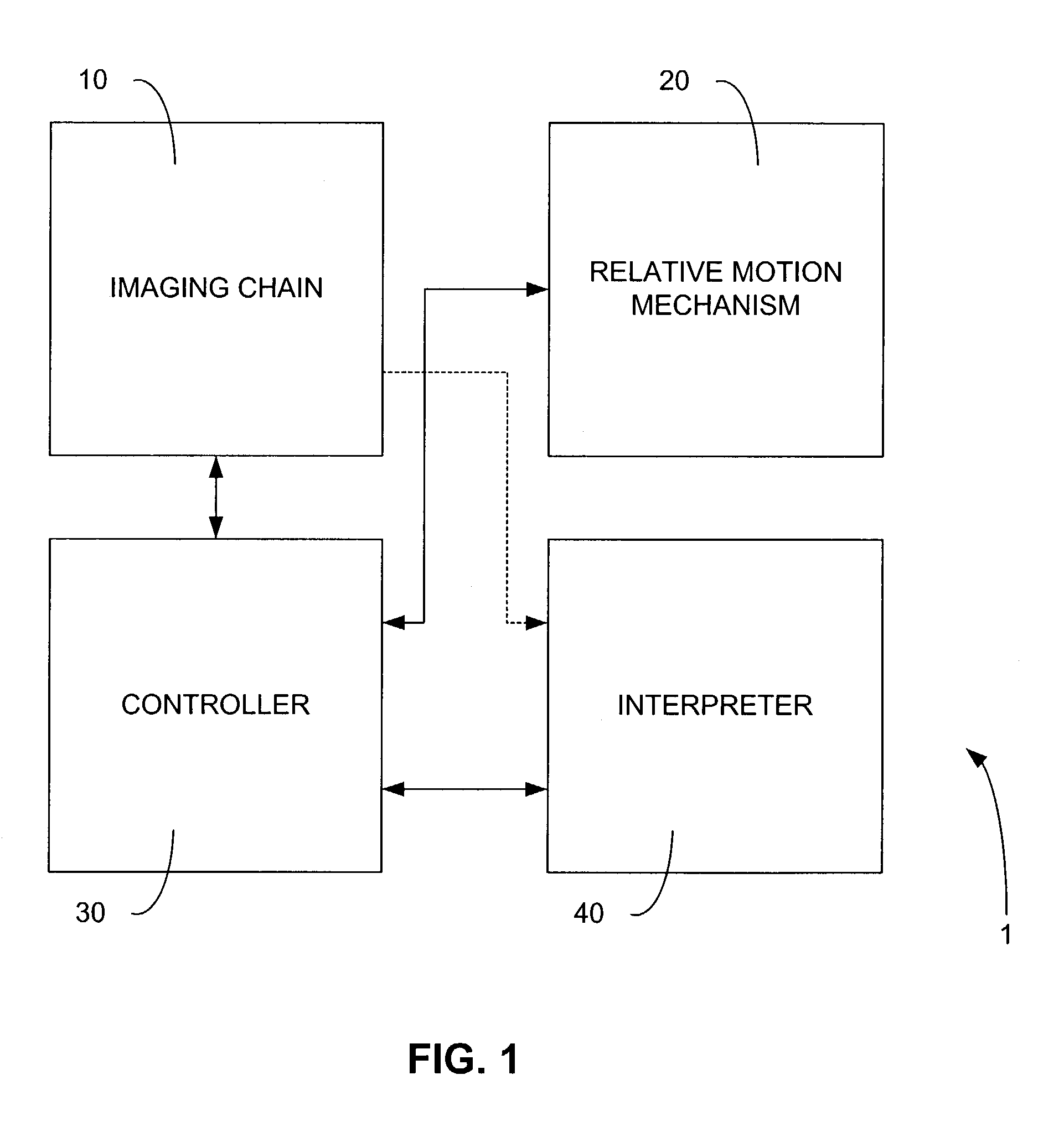
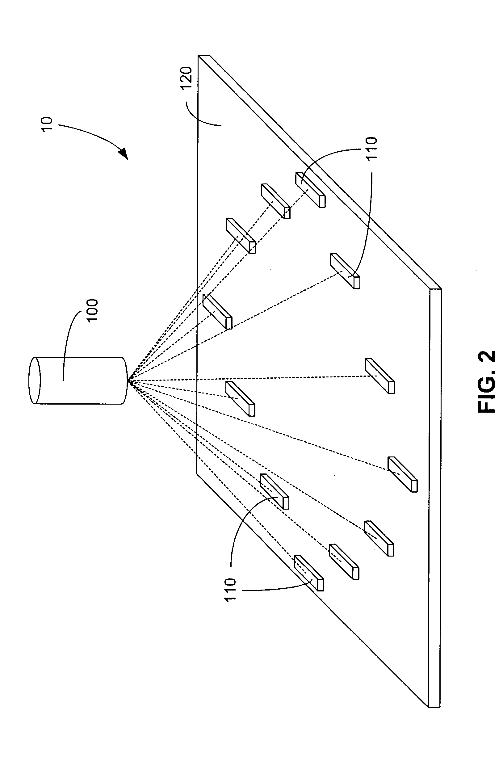
[0015]An example of an x-ray inspection system 1 according to an embodiment of the invention is shown in FIG. 1. An imaging chain 10 is employed to obtain x-ray images of an article under inspection. In this particular embodiment, the article is an electronic printed circuit board (PCB). In other embodiments, any article of manufacture susceptible to inspection by the use of x-rays may be inspected by such a system. A relative motion mechanism 20 is used to maneuver the article under inspection in relation to the imaging chain 10 so that various areas of the article may be inspected. In other embodiments, the relative motion mechanism 20 moves the imaging chain 10 in relation to a stationary article. An interpreter 40 then takes the x-ray images as input to generate a series of layer images, each exposing a separate conceptual “layer” of the article. The interpreter 40 may then process such images in order to ascertain the overall quality of the article under inspection by comparing...


PUM


Abstract

An x-ray inspection is provided featuring a single x-ray source and a planar array of linear sensors aligned in parallel. An article to be inspected is moved between the x-ray source and the linear sensors in a series of passes parallel to the array of linear sensors and substantially perpendicular to the long axes of the linear sensors. Alternately, the x-ray source and the sensors are moved as a unit relative to a stationary article. As a result, a transmission image of the article is captured for each of the linear sensors. These transmission images are then combined mathematically to generate a layer image for each separate conceptual layer of the article. In some embodiments, these layer images may then be interpreted in order to determine the quality of the article.

Description

BACKGROUND OF THE INVENTION[0001]For some years now, three-dimensional (3-D) x-ray inspection systems have been a popular alternative to previously available physical inspection and diagnosis technologies: Such systems are now commonly used for defect analysis and quality inspection of manufactured articles, such as electronic printed circuit boards (PCBs). The use of these systems allows rather detailed inspection of areas of an article that are either too small to be seen with the naked eye, or are obscured from direct view.[0002]Several types of 3-D x-ray inspection systems are now available, each with their own inherent advantages and limitations. For example, x-ray laminography systems, such as the one described in U.S. Pat. No. 4,926,452 by Baker et al., utilize an angled, rotating x-ray source in conjunction with a moving area image detector to acquire an image of a single planar layer of an article under inspection. Due to the rotational movement of the source and the image ...

Claims


Application Information

Patent Timeline
IPC IPC(8): G01N23/02G01N23/04
CPCG01N23/04G01N23/044A61B6/00
Inventor MEYER, GERALD L
Owner AGILENT TECH INC
Why Eureka
Try Eureka