Coupled optical waveguide resonators with heaters for thermo-optic control of wavelength and compound filter shape

a thermo-optic control and heater technology, applied in the direction of optical waveguide light guide, instruments, optics, etc., can solve the problems of large dn/dt, unsuitable materials with high dn/dt magnitudes greater, and inconvenient use of thermo-optic devices requiring precise control of resonant frequency of better than 1 ghz

Active Publication Date: 2007-06-12
INFINERA CORP
View PDF6 Cites 22 Cited by
  • Summary
  • Abstract
  • Description
  • Claims
  • Application Information

AI Technical Summary

Problems solved by technology

Applications of optical resonator thermo-optic devices requiring precise control of resonant frequency of better than ±1 GHz are not well suited to materials with high dn / dT magnitudes greater than about 5×10⁻⁵.
A large dn / dT in this case is not desirable as it will require very precise local temperature control on the order of 0.1° C. Low dn / dT magnitudes of less than about 1×10⁻⁵, however, require somewhat more power as larger local temperature changes are needed to achieve a desired refractive index change, Δn.
This method becomes unwieldy for a complex integrated optical device and would involve multiple real time optical measurements for the elements within the device.
Although it is relatively straightforward to control the resonant wavelength of a single ring resonator using a heater and a temperature sensor, compound optical resonators comprising at least two optically coupled resonators are more complex.
There are two major limitations of this design.
Two, it is difficult to devise a large area heater that produces a laterally uniform temperature profile across a set of coupled resonators and over a reasonably large temperature range of many tens of degrees Celsius.
The result would be a deterioration in the compound filter shape from optimum.
First, each optical resonator within the integrated optical device would need its own heater and temperature sensor.
This greatly increases the number of electrical connections required by the optical chip.
The small separation means that there will be significant thermal crosstalk between the temperature sensor of one resonator and the heaters of adjacent resonators that results in control loop instability.

Method used


Image

  • Coupled optical waveguide resonators with heaters for thermo-optic control of wavelength and compound filter shape
  • Coupled optical waveguide resonators with heaters for thermo-optic control of wavelength and compound filter shape
  • Coupled optical waveguide resonators with heaters for thermo-optic control of wavelength and compound filter shape

Examples


Embodiment Construction

[0032]Presently preferred embodiments of the invention are shown in the above-identified figures and described in detail below. In describing the preferred embodiments, like or identical reference numerals are used to identify common or similar elements. That is, the reference numerals include similar numeric prefixes and different alphabetic suffixes to specifically identify particular elements in the drawings. The numeric prefix by itself refers to a group of elements and not to any particular element. The figures are not necessarily to scale and certain features and certain views of the figures may be shown exaggerated in scale or in schematic in the interest of clarity and conciseness.

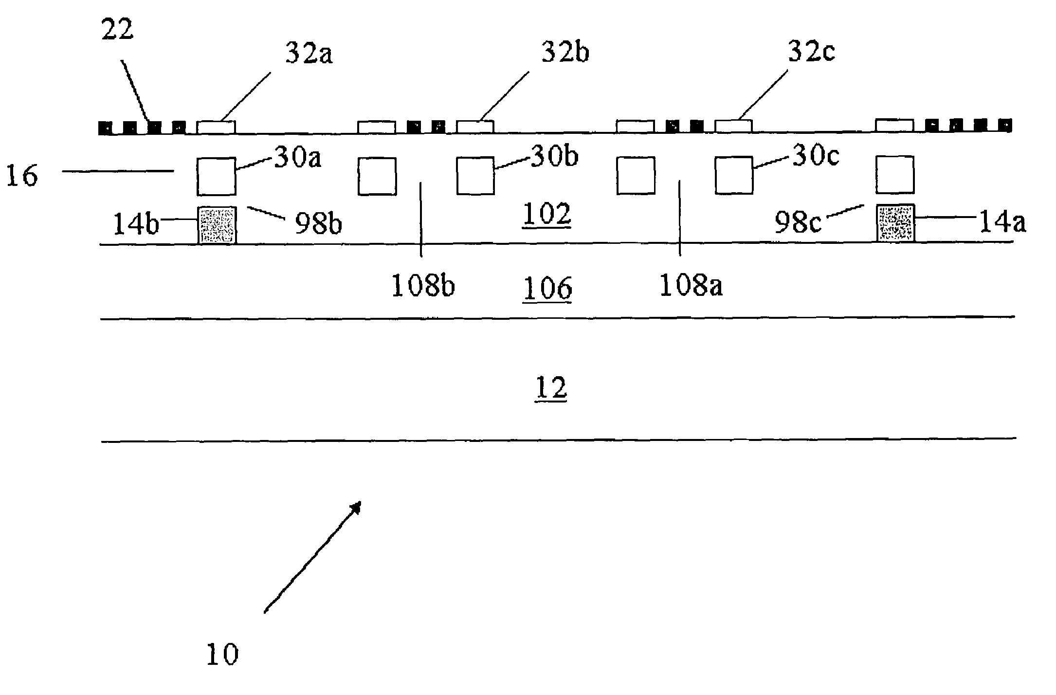
[0033]Referring now to the drawings, and more particularly to FIGS. 5 and 6, shown therein is an integrated optical device 10 constructed in accordance with the present invention. The integrated optical device 10 is provided with a substrate 12, at least one optical waveguide 14 (two are shown and ...


PUM

PropertyMeasurementUnit
resistanceaaaaaaaaaa

Abstract

An integrated optical device is disclosed comprising a substrate, optical waveguide, and compound optical resonator having a temperature sensor, at least two coupled optical resonators, and a heater localized to each optical resonator. An optical input signal is coupled to one of the resonators making up the compound resonator to form an optical output signal. The center wavelength and shape of the output signal is optimized with a feedback loop using the temperature sensor to control the power dissipated in at least one of the localized heaters. The power dissipated in the remaining resonator heaters is set according to a predetermined function having as an input variable the power dissipated in the resonant heater under control of the said feedback loop.

Description

BACKGROUND OF THE INVENTION[0001]1. Field of the Invention[0002]This invention pertains to integrated optical circuits having optical waveguides wherein a portion of the optical waveguides' refractive index is adjusted thermo-optically. More particularly, this invention pertains to thermo-optic control of the transfer function of a compound optical resonator by use of individual heaters localized to each resonator waveguide element and a local temperature sensor.[0003]2. Description of the Related Art[0004]The field of integrated optics has expanded tremendously over the past decade, and integrated optical device solutions are now being proposed for applications in a variety of fields including: telecommunications, data communications, high performance computing, biological and chemical sensing, and RF networks. Long haul, metropolitan, and local networks, as well as fiber-to-the-home applications, predominately rely on optical communications for data transmission. Wavelength divisi...

Claims


Application Information

Patent Timeline
Patent Type & Authority Patents(United States)
IPC IPC(8): G02B6/02G02F1/295
CPCG02B6/12007G02F1/0147G02F1/3132
Inventor CHU, SAIJOHNSON, FREDERICK G.KING, OLIVERSCHUETZ, MARCUSLITTLE, BRENT
Owner INFINERA CORP
Why Eureka
Try Eureka