Spurious ratio control circuit for use with feed-forward linear amplifiers

a technology of ratio control circuit and linear amplifier, which is applied in the direction of amplifier modification to reduce non-linear distortion, transmission, transmission monitoring, etc., can solve the problems of integer multiples of original carrier frequency sum and difference of spurious outputs, and achieve the effect of optimizing the adjustment of error-canceling loop and minimizing the ratio of the second spurious component to the first spurious componen

Inactive Publication Date: 2007-06-12
INTEL CORP
View PDF14 Cites 11 Cited by
  • Summary
  • Abstract
  • Description
  • Claims
  • Application Information

AI Technical Summary

Benefits of technology

[0015]In accordance with still another aspect of the present invention, a method of adjusting a linear feed-forward amplifier, the method comprising, monitoring a first spurious component at a first monitoring point by a control system, monitoring a second spurious component at a second monitoring point by the control system, comparing the levels of the second spurious component to the first spurious component to form a ratio, and adjusting the feed-forward linear amplifier through a control output of the control system is provided. Whereby, the ratio of the second spurious component to the first spurious component is minimized, thus optimizing the adjustment of the error-canceling loop.
[0016]In accordance with a further aspect of the present invention a method of adjusting the predistorter of a feed-forward amplifier having a first monitoring point coupled to the predistorter output, a second monitoring point coupled to the output of the first loop, a control system having a first input coupled to the first monitoring point, a second input coupled to the second monitoring point, a third input coupled to a source of frequency information, and its control outputs coupled to the control inputs of the feed-forward linear amplifier. The method comprises monitoring a first spurious component at the first monitoring point by the control circuit, monitoring a second spurious component at the second monitoring point by the control circuit, comparing the levels of the second spurious component to the first spurious component in the control circuit to form a ratio, and adjusting the control inputs of the feed-forward linear amplifier so that the ratio of the spurious component of the second spurious component to the first spurious component is minimized, thus optimizing the adjustment of the predistorter.

Problems solved by technology

One possible source of such cross-channel interference is known as intermodulation distortion (IMD), which may result when two or more signals of different frequencies are mixed.
For example, if two carriers of different frequencies are amplified using a non-linear amplifier, spurious outputs occur at the sum and difference of integer multiples of the original carrier frequencies.

Method used


Image

  • Spurious ratio control circuit for use with feed-forward linear amplifiers
  • Spurious ratio control circuit for use with feed-forward linear amplifiers
  • Spurious ratio control circuit for use with feed-forward linear amplifiers

Examples


first embodiment

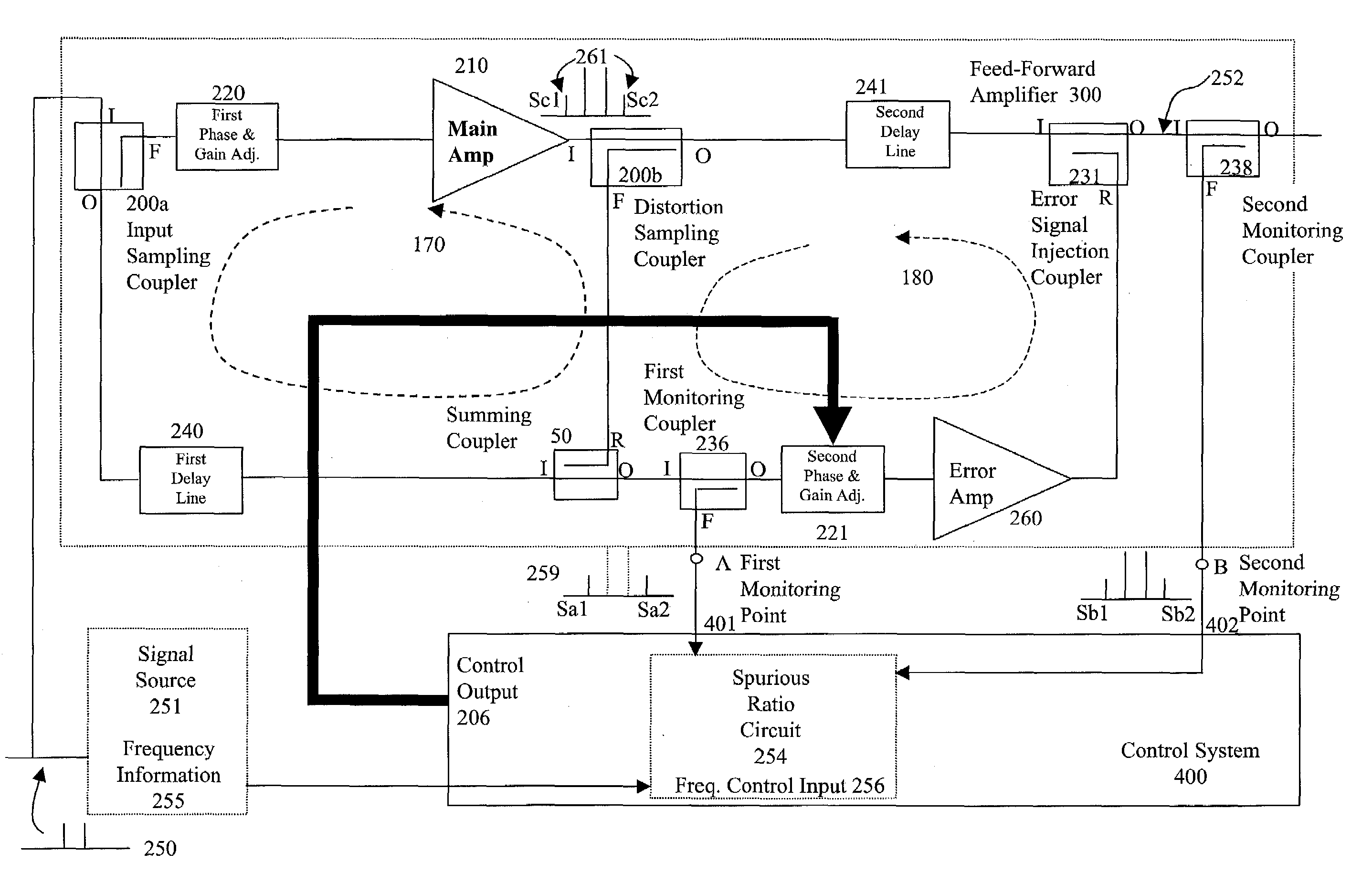
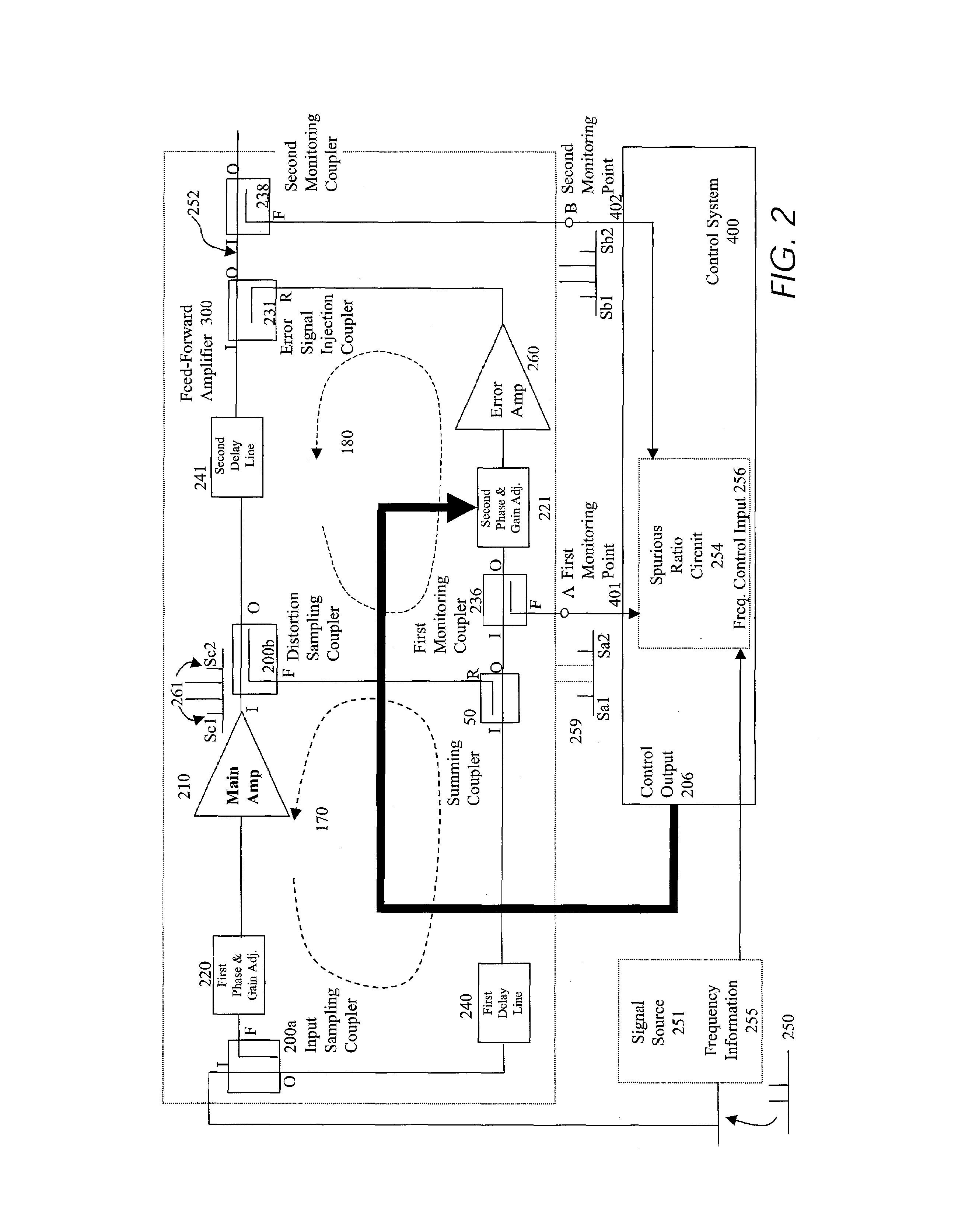
[0035]FIG. 2 is a feed-forward amplifier system having a control system 400 including a spurious ratio circuit 256. The spurious ratio circuit 256 is coupled to a feed-forward amplifier 257, such as a feed-forward power amplifier, at two monitoring points. The feed-forward amplifier has two monitoring points at A and B. The control system 400 produces an output that is coupled to phase and gain adjustment circuits in the feed-forward amplifier. Frequency information derived from an input signal source 251 is coupled to the spurious detection circuit 254.

[0036]Prior knowledge of the frequencies being transmitted is utilized by the spurious detection circuit to measure distortion. In many communication systems such as cellular telephone systems, for example, the frequencies being amplified and subsequently transmitted are known. Transmitting frequency information is typically available from a bank of synthesizers, and is often available over a control bus. Exemplary control buses incl...

second embodiment

[0073]FIG. 6 is a block diagram of a feed-forward amplifier with a spurious ratio detector, including a switch to periodically sample monitoring points B and C (point A being monitored continuously). Where an adaptive predistorter 305 is included, the ratios A / C and B / A are measured. A first input of the spurious detector 254 is directly coupled to monitoring point A, a second input of the spurious detector 254 is coupled to the output of a switch 501. Monitoring point C is coupled to a first input of switch 501. Monitoring point B is coupled to a second input of switch 501. The switch 501 switches between C and B.

third embodiment

[0074]FIG. 7 is a block diagram of the feed-forward amplifier including a spurious ratio detector with a single receiver and a three way switch to periodically sample monitoring points A, B and C. This embodiment is used where the signal dynamics tend to be slow. It may be used in place of the two receiver design shown in the spurious detection circuit (254 of FIG. 5). A single receiver such as 430, 410 and 421 of FIG. 5 is used to form receiver 503. Sampling is achieved by switching the single receiver 503 between two or three of the monitor points A, B and C, and sequentially sampling the distortion power from each.

[0075]A single receiver 503 typically comprises a conventionally constructed mixer having a distortion signal coupled to a first input port, and a second input port coupled to an output port of a conventionally constructed local oscillator. A mixer output port is coupled to an input port of a conventionally constructed band pass filter. A band pass filter output is coup...


PUM


Abstract

A control system for a linear feed-forward amplifier, using the ratio of measured spurious energy. Measuring receivers are coupled to two monitoring points to measure the spurious energy content in the error signal and at the main output of a feed-forward amplifier. The control system measures the ratio of these detected spurious, and uses this to optimize the settings of the second loop distortion cancellation. With the addition of an extra monitoring point, the same technique may also be used to control an adaptive predistorter prior to the main amplifier.

Description

CROSS-REFERENCE TO RELATED APPLICATION[0001]This application claims the benefit of U.S. Patent Application No. 60,325,627, filed Sep. 28, 2001, the contents of which are hereby incorporated by reference.BACKGROUND OF THE INVENTION[0002]The present invention relates to electronic communication systems, and more particularly to systems in which multiple signals are simultaneously transmitted at varying power levels.[0003]In electronic communication systems, it is often necessary that groups of information signals be amplified and transmitted simultaneously. For example, a cellular radio base station transmitter typically transmits signals to many active receiving mobile stations within a single geographic cell. The signals typically appear at multiple predetermined frequencies in such multi-carrier signals. Similarly, a satellite communications transponder amplifies and transmits large number of information signals destined for various participating remote stations. Because such syste...

Claims


Application Information

Patent Timeline
Patent Type & Authority Patents(United States)
IPC IPC(8): H04B1/04H03F1/32H04B1/02
CPCH03F1/3229H03F1/3247
Inventor POSNER, RICHARD D.WILKINSON, ROSS JAMES
Owner INTEL CORP
Why Eureka
Try Eureka