Integrated motorized pump

a motorized pump and integrated technology, applied in the direction of piston pumps, positive displacement liquid engines, liquid fuel engines, etc., can solve the problems of increasing the amount of heat energy to be dissipated by air coolers, increasing the size of electronic components, and increasing etc., to achieve the effect of avoiding slippage, and reducing the cost of operation

Inactive Publication Date: 2007-06-19
ROTYS
View PDF11 Cites 42 Cited by
  • Summary
  • Abstract
  • Description
  • Claims
  • Application Information

AI Technical Summary

Benefits of technology

[0008]The objectives of the present invention are to realize an electric integrated combination m...

Problems solved by technology

During normal operation many electronic components generate significant amounts of heat.
If this heat is not continuously removed, the component may overheat resulting in damage and/or reduction in operating performance...

Method used


Image

  • Integrated motorized pump
  • Integrated motorized pump
  • Integrated motorized pump

Examples


Embodiment Construction

[0036]Preferred embodiments of the present invention will be described in detail below with reference to the accompanying drawings.

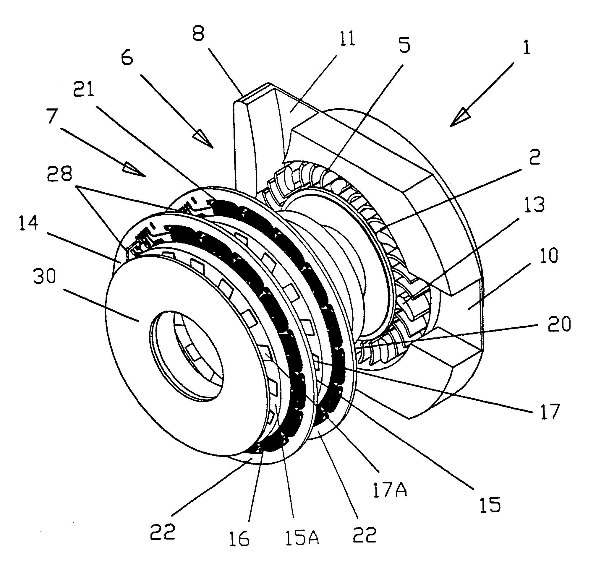
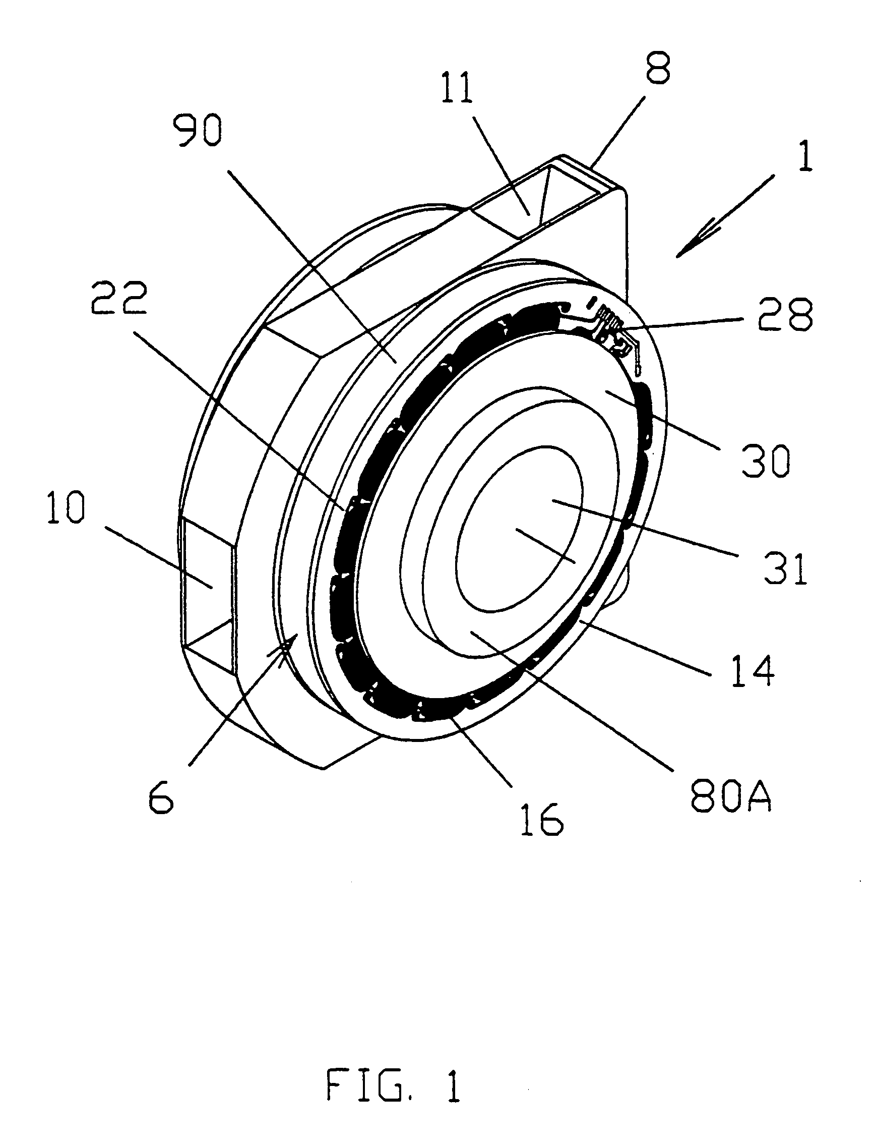
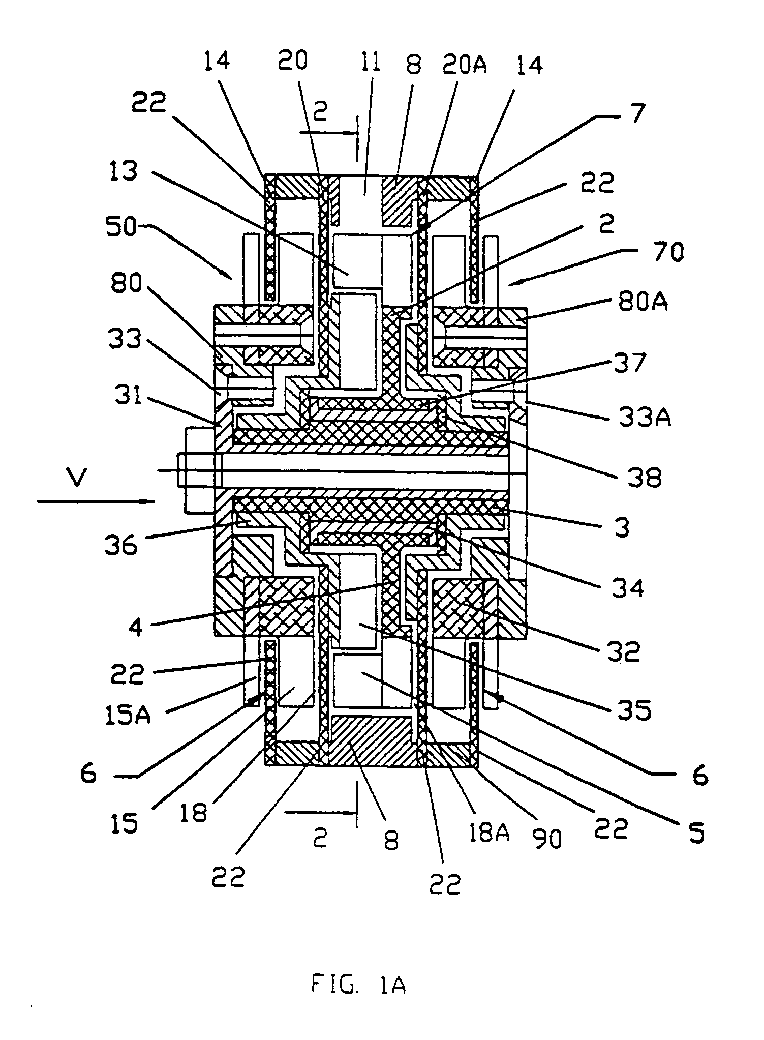
[0037]An integrated motorized pump 1 (FIGS. 1-3) comprises: an impeller 2 that is mounted on an axle 3, two magnetic drives 6 electro magnetically coupled with an electric motor 7, and a casing 8 with a flowing space 9 and inlet channel 10 and outlet channel 11.

[0038]The impeller 2 (FIGS. 1A, 2-4, 7, 10 and 11) may be a different type as will be described further and has one impeller disk 4 and blades5 attached to the impeller disk 4. The impeller 2 placed inside the casing 8 and along with the flowing space 9, inlet and outlet channels 10 and 11 forms pump flowing part 12. The blades 5 are magnetized in the direction parallel to the axle 3 and serves as circumferential arrayed magnetic means 13.

[0039]Each of two magnetic drives 6 (FIGS. 1, 1a, 3 and 6) includes one stator 14 and two magnetized disk 15 and 15A. The stator 14 (FIGS. 1, 1A, 3, 6, 8, 10 and...


PUM


Abstract

An integrated motorized pump (1) comprising an impeller (2) mounted on an axle (3), two magnetic drives (6) electromagnetically coupled to an electric motor (7), a casing (8) with a flowing space (9), an inlet channel (10) and an (11). The impeller (2) has circumferential arrayed magnetic means (13) magnetized in the direction parallel to the axle (3). The electric motor (7) comprising said impeller (2) as a rotor, and two stator plates (20). The stator plates (20) are covered with a liquid tight coating and comprise circumferential arrayed coils (21) etched on circuit board metal layers (22). Each magnetic drive (6) comprises a stator (14) with circumferential arrayed coil windings (16) and two magnetized disks (15). The magnetized disks (15) are mounted on the axle (3) perpendiculary to it and have a circumferential carry of radially extending poles (17).

Description

CROSS REFERENCE TO RELATED APPLICATIONS[0001]This application is a U.S. National Phase Application under 35 USC 371 of International Application PCT / U502 / 026711 filed Aug. 20, 2002 which claims the benefit of priority of U.S. Provisional Patent Application Ser. No. 60 / 314,016, filed Aug. 21, 2001.FIELD OF THE INVENTION[0002]The invention covered by this application is related generally to magneto electric pumps, in particular, to pumps for liquid cooling, and may be used in the manufacture of liquid pumps for various purposes, e.g. liquid cooling of electronic components, car board pumps, fuel pumps etc.BACKGROUND OF THE INVENTION[0003]During normal operation many electronic components generate significant amounts of heat. If this heat is not continuously removed, the component may overheat resulting in damage and / or reduction in operating performance. In order to avoid such problems cooling devices are often used in conjunction with these components.[0004]One such cooling device is...

Claims


Application Information

Patent Timeline
IPC IPC(8): F04B17/00F04B35/04F04D5/00F04D13/06
CPCF02M37/048F04D5/002F04D13/0666F04D29/586
Inventor LOPATINSKY, EDWARD L.SHAEFER, DAN K.ROSENFELD, SAVELIY T.FEDOSEYEV, LEV A.
Owner ROTYS
Why Eureka
Try Eureka