Biosensor, measuring instrument for biosensor, and method of quantifying substrate

a biosensor and measuring instrument technology, applied in the field of biosensors, can solve the problems of affecting the measurement device, reducing the measurement accuracy, and z-type biosensors have some problems to be solved

Inactive Publication Date: 2007-06-19
PHC HLDG CORP
View PDF22 Cites 170 Cited by
  • Summary
  • Abstract
  • Description
  • Claims
  • Application Information

AI Technical Summary

Problems solved by technology

However, the conventional biosensor Z has some problems to be solved.
First, an incorrect operation by a user influences them.
Second, characteristics of an object to be measured influence them.
Third, a temperature around the measuring device influences them.
A sharp change in temperature influences the oxidation current corresponding to a substrate concentration, and thus may lower the measurement accuracy.

Method used


Image

  • Biosensor, measuring instrument for biosensor, and method of quantifying substrate
  • Biosensor, measuring instrument for biosensor, and method of quantifying substrate
  • Biosensor, measuring instrument for biosensor, and method of quantifying substrate

Examples


exemplary embodiment 1

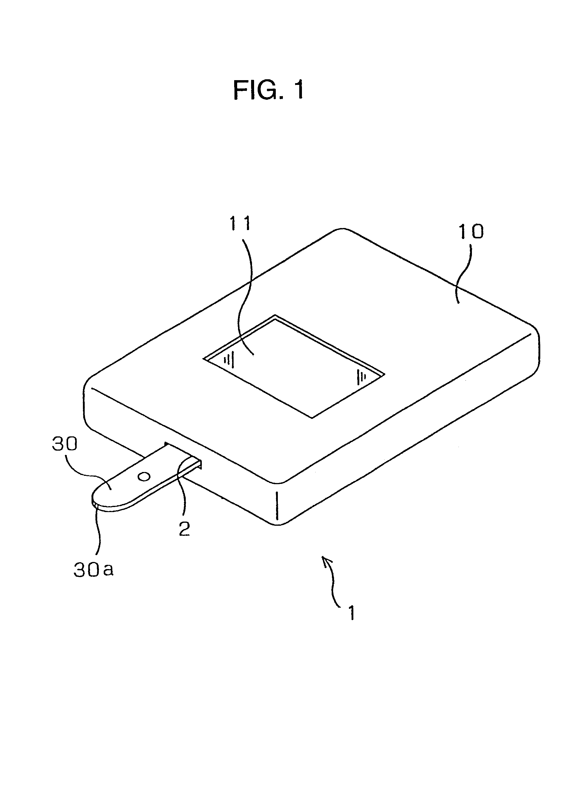
[0053]The first embodiment will be demonstrated hereinafter with reference to the accompanying drawings. FIG. 1 shows a biosensor system in accordance with the first embodiment of the present invention. Biosensor system 1 includes biosensor 30 and measuring device 10 having biosensor 30 mounted detachably thereto. Sample liquid is dripped on sample-drip point 30a located at a tip of biosensor 30. A quantity of a substrate included in the dripped sample liquid is measured by measuring device 10.

[0054]Measuring device 10 includes, for instance, supporting section 2 to which biosensor 30 is detachably mounted and display 11 which shows a measured quantity of the substrate included in the sample liquid dripped on sample-drip point 30a.

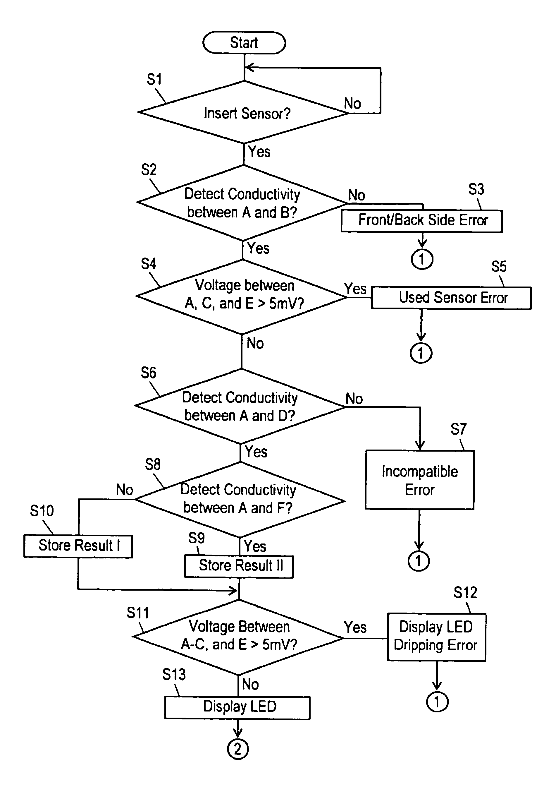
[0055]To measure a quantity of a substrate included in sample liquid with biosensor system 1, first, a user inserts biosensor 30 into measuring device 10. Then the user drips the sample liquid on sample-drip point 30a while measuring device 10 applies a c...

exemplary embodiment 2

[0133]The biosensor in accordance with the second exemplary embodiment will be demonstrated hereinafter. In this embodiment, an enzyme sensor is described. The sensor employs an enzyme as a molecule recognizing element which specifically reacts on a specific material contained in sample liquid.

[0134]An incorrect operation by a user influences a measuring accuracy. Thus the second embodiment discusses this problem. In particular, a user fails to drip sample liquid to an inlet of a sample supplying path, and the sample liquid attaches to a surrounding areas of the inlet. As a result, the sample supplying path cannot carry the sample liquid. Such kind of incorrect operations by a user may affect a measurement accuracy, and the ways how to avoid those mis-operations are demonstrated in this embodiment.

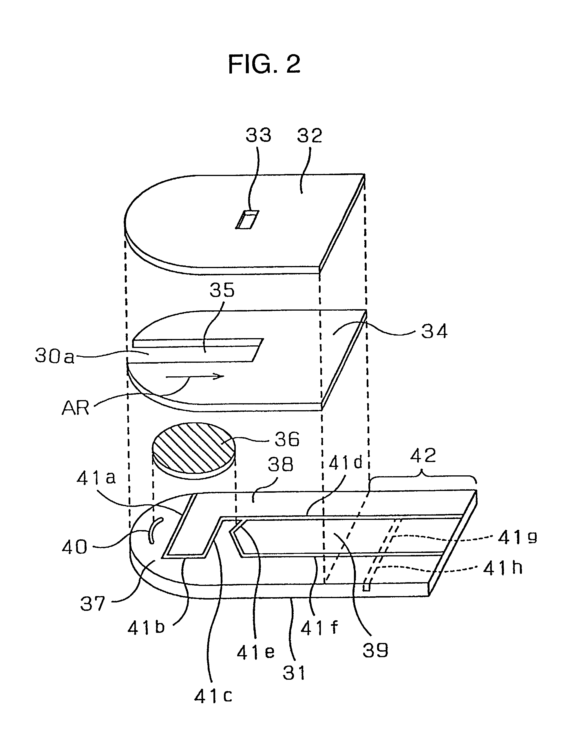
[0135]According to a structure shown in FIG. 16 or FIG. 2, at the inlet, to which sample liquid is supplied, of the sample supplying path, an insulating board and a cover forming the path ...

example 1

[0157]A thin palladium film of 8 nm thickness was formed on the entire surface of the first insulating board made of polyethylene terephthalate by sputtering evaporation method. Then slits were provided on a part of the thin film by YAG laser, and thus the electrode was divided into a measuring electrode, a counter electrode and a detecting electrode. On top of that, water solution containing enzymes, electron carriers, and hydrophilic high-polymer was dripped such that the water solution covered the measuring electrode as a center and parts of the counter electrode as well as the detecting electrode. Then the water solution was dried to form a reagent layer. Further on top of that, a spacer made of polyethylene terephthalate and having a notch together with the second insulating board (cover) made of polyethylene terephthalate and having the air hole was bonded. As a result, the sample supplying path, i.e., a capillary which leads blood, was formed.

[0158]In order to confirm the adv...


PUM

PropertyMeasurementUnit
volume %aaaaaaaaaa
volume %aaaaaaaaaa
voltageaaaaaaaaaa

Abstract

A biosensor, a measuring instrument for biosensor, and a method of quantifying a substrate contained in specimen liquid to reduce a measurement error by the biosensor; a biosensor, comprising at least a pair of electrodes formed on an insulation substrate; a measuring instrument, comprising a supporting part for detachably supporting the biosensor, a plurality of connection terminals electrically connected to the electrodes, and a drive power supply for applying a voltage to the electrodes through the connection terminals; wherein the biosensor is inserted into the measuring instrument, either one of the electrodes of the biosensor is connected to first and second connection terminals fined to the measuring instrument only when the biosensor is inserted into the support part of the measuring instrument in a specified direction and has an electrode structure to allow the first connection terminal to conduct with the second connection terminal when a voltage is applied by the drive power supply.

Description

CROSS-REFERENCE TO RELATED APPLICATIONS[0001]This application is a U.S. national phase of PCT Application No. PCT / JP01 / 10525, filed Nov. 30, 2001, and claims priority to Japanese Application No. 2000-364225, filed Nov. 30, 2000 and Japanese Application No. 2001-357144, filed Nov. 22, 2001.TECHNICAL FIELD[0002]The present invention relates to a biosensor for measuring the quantity of a substrate included in sample liquid and a measuring device for the biosensor. Further, the present invention provides a novel measuring method which reduces measurement errors caused by a biosensor.BACKGROUND ART[0003]Biosensors measure the quantity of a substrate included in sample liquid. The sensors utilize molecular recognition capability of bio material such as germ, enzyme, antibody, DNA, RNA and the like, and uses the bio material as a molecular recognizing element. In other words, when the bio material recognizes an objective substrate, it reacts such that the germ breathes, emits light, consum...

Claims


Application Information

Patent Timeline
Patent Type & Authority Patents(United States)
IPC IPC(8): G01N27/327A61B5/00G01N33/487
CPCC12Q1/001C12Q1/005G01N27/327G01N27/3272G01N33/48771G01N33/5438C12Q1/006A61B5/1486A61B2562/0295G01N27/26G01N27/3274
Inventor MIYAZAKI, SHOJITOKUNAGA, HIROYUKITOKUNO, YOSHINOBUMATSUMOTO, KAZUHIROSAWADA, YASUHIKO
Owner PHC HLDG CORP
Why Eureka
Try Eureka