High-mounted double wishbone suspension device

a suspension device and double wishbone technology, applied in the direction of suspensions, resilient suspensions, vehicle components, etc., can solve the problems of the weight corresponding to the dynamic damper, easy transmission of vibration, etc., and achieve the effect of reducing road noise, without increasing the number of components or the weigh

Inactive Publication Date: 2007-06-26
HONDA MOTOR CO LTD
View PDF12 Cites 12 Cited by
  • Summary
  • Abstract
  • Description
  • Claims
  • Application Information

AI Technical Summary

Benefits of technology

[0008]The present invention has been accomplished under the above-mentioned circumstances, and it is an object thereof to reduce the road noise transmitted by a high-mounted double wishbone suspension device without increasing the number of components or the weight.
[0012]With the arrangement of the first aspect, in the high-mounted double wishbone suspension device in which the knuckle is supported vertically movably via the lower arm and the upper arm, the tie rod connection portion is provided in the arm portion to extend upward from the knuckle main body portion through which the axle runs, and the tie rod for turning the wheel is connected to the tie rod connection portion. Therefore, it is possible for the tie rod to effectively suppress knuckle lateral vibration centered on the axle by increasing the distance from the axle to the tie rod connection portion, thereby reducing the road noise without increasing the number of components or the weight.
[0013]With the arrangement of the second aspect, since the tie rod is joined to the joint provided on the lower face of the tie rod connection portion, it is possible to minimize vertical positional change of the tie rod while suppressing lateral vibration of the knuckle by raising the position of the tie rod connection portion, whereby the arrangement can be easily applied to a conventional vehicle merely by changing the knuckle alone.

Problems solved by technology

In a so-called high-mounted double wishbone suspension device in which an arm portion extending upward from a knuckle is made to project above a tire and the upper end of the arm portion is connected to the extremity of an upper arm, since it is necessary to connect the base end of the upper arm to an inner face of a wheelhouse, vibration in the vicinity of a certain frequency (e.g., 300 Hz) input from the road surface to the tire is transmitted from the knuckle through the upper arm to the wheelhouse, leading to a problem that the vibration is easily transmitted as road noise to the interior of a vehicle compartment.
However, in the conventional arrangement, the dynamic damper is used for suppressing the vibration of the upper arm, leading to a problem that the number of components and the weight are increased corresponding to the dynamic damper.

Method used


Image

  • High-mounted double wishbone suspension device
  • High-mounted double wishbone suspension device
  • High-mounted double wishbone suspension device

Examples


Embodiment Construction

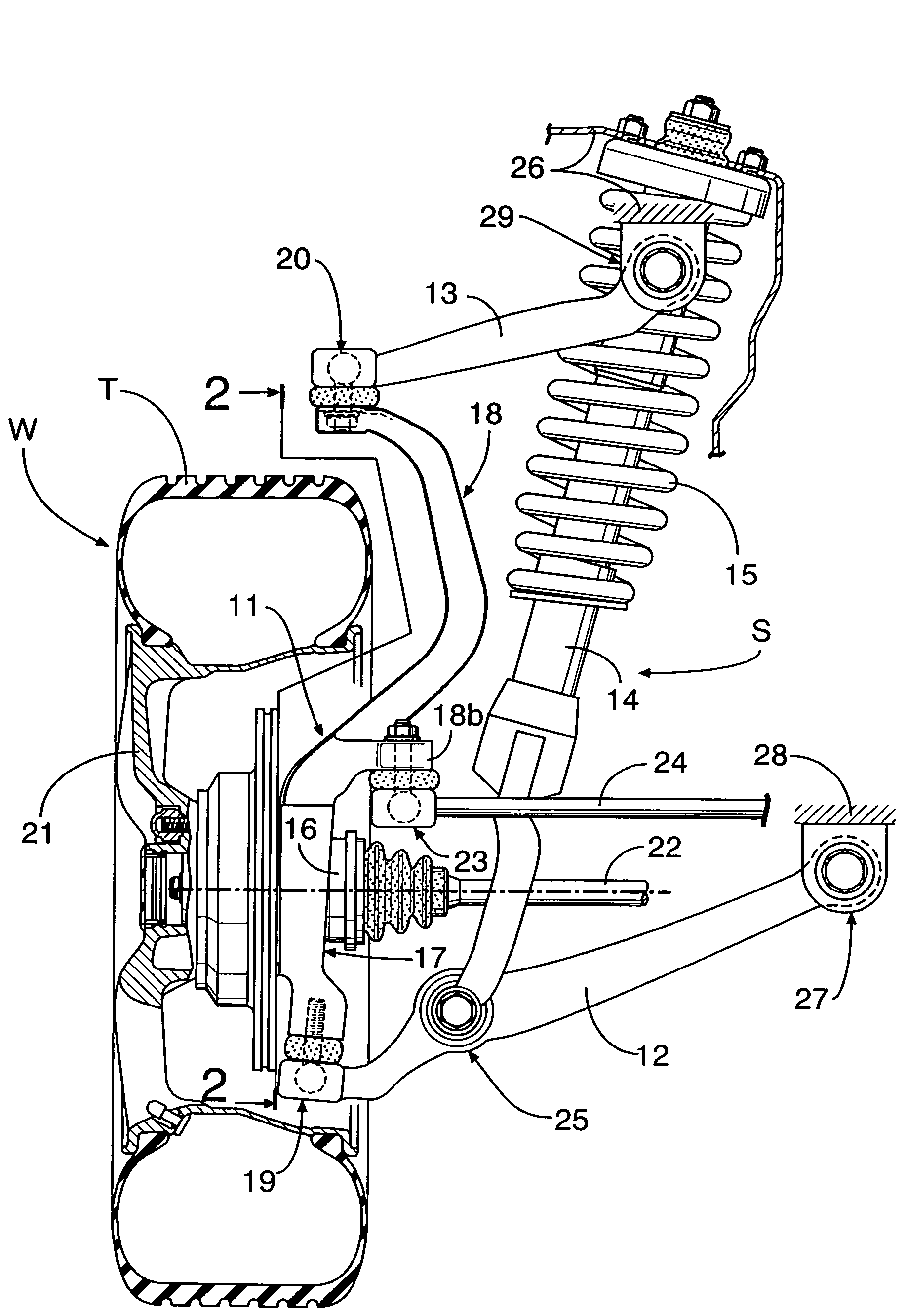
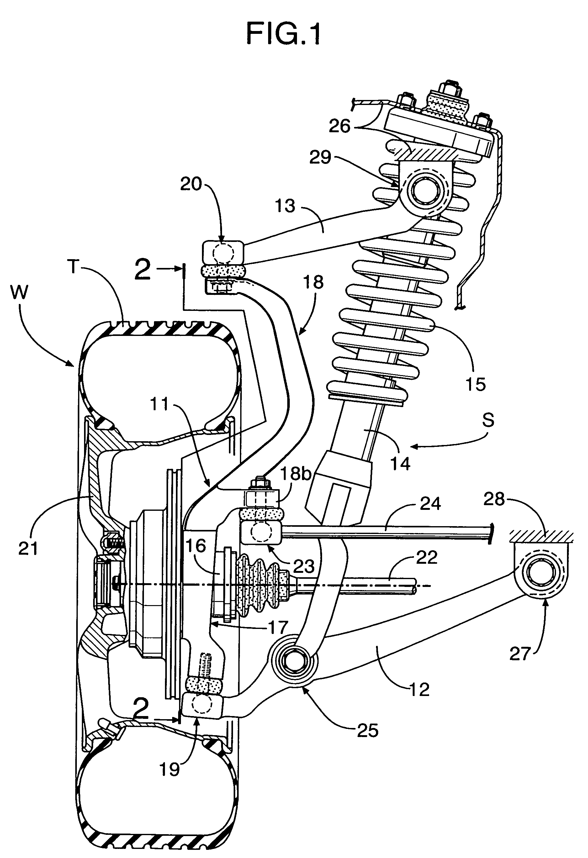
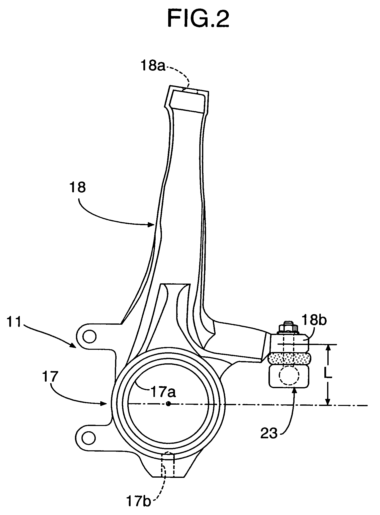
[0020]FIG. 1 and FIG. 2 show a high-mounted double wishbone suspension device for suspending a front wheel W which is a driven wheel. The high-mounted double wishbone suspension device includes: a knuckle 11; a lower arm 12; an upper arm 13; a hydraulic damper 14; and a suspension spring 15. The knuckle 11 is formed from: a knuckle main body portion 17 for rotatably supporting an axle 16 via a ball bearing (not illustrated); and an arm portion 18 extending upward from the knuckle main body portion 17 over a tire T of the front wheel W. Formed in the middle of the knuckle main body portion 17 is a ball bearing support hole 17a into which the ball bearing is fitted. Formed in the lower end of the knuckle main body portion 17 is a mounting hole 17b for receiving a ball joint 19 that pivotably supports the extremity of the lower arm 12. Formed in the upper end of the arm portion 18 is a mounting hole 18a for mounting a ball joint 20 that pivotably supports the extremity of the upper arm...


PUM


Abstract

In a high-mounted double wishbone suspension device, an arm portion extending upward from a knuckle main body portion, through which an axle runs, is provided with a tie rod connection portion. A tie rod for turning a wheel is connected to the tie rod connection portion. The distance between the axle and the tie rod connection portion is increased to effectively suppress knuckle lateral vibration centered on the axle by the tie rod. Therefore, it is possible to reduce road noise without increasing the number of components or the weight. In particular, since the tie rod is connected to a joint provided on a lower face of the tie rod connection portion, it is possible to minimize vertical positional change of the tie rod, while suppressing lateral vibration of the knuckle by raising the position of the tie rod connection portion, whereby the arrangement can be easily applied to a conventional vehicle merely by replacing the knuckle alone.

Description

RELATED APPLICATION DATA[0001]The Japanese priority application No. 2003-417548 upon which the present application is based is hereby incorporated in its entirety herein by reference.BACKGROUND OF THE INVENTION[0002]1. Field of the Invention[0003]The present invention relates to a high-mounted double wishbone suspension device comprising: a knuckle rotatably supporting a wheel, and comprising a knuckle main body portion and an arm portion extending upward from the knuckle main body portion; a lower arm vertically movably supporting on a vehicle body a lower part of the knuckle main body portion through which an axle runs; and an upper arm vertically movably supporting on the vehicle body the arm portion.[0004]2. Description of the Related Art[0005]In a so-called high-mounted double wishbone suspension device in which an arm portion extending upward from a knuckle is made to project above a tire and the upper end of the arm portion is connected to the extremity of an upper arm, since...

Claims


Application Information

Patent Timeline
Patent Type & Authority Patents(United States)
IPC IPC(8): B62D7/16B60G7/00B60G3/20B62D7/18
CPCB60G3/20B62D7/18B60G2200/144B60G2204/129B60G2204/143
Inventor YAMAZAKI, TATSUYAHIRATA, HIROKAZUHOZUMI, YUTAKAMAEJIMA, AKIHIRO
Owner HONDA MOTOR CO LTD
Why Eureka
Try Eureka