Supercharge Your Innovation With Domain-Expert AI Agents!

Method for increasing operating efficiency of the rotor blade of an aerogenerator (variants)

a technology of rotor blade and variable speed, which is applied in the field of wind energy, can solve the problem that the boundary layer control cannot be used for the rotor blade of a wed with a horizontal axis of rotation, and achieve the effect of optimizing the value of suction withdrawal of air, effective neutralizing the action, and enhancing the effectiveness of the rotor blad

Inactive Publication Date: 2007-06-26
LNS WINDBLADE TECH LLC
View PDF8 Cites 16 Cited by
  • Summary
  • Abstract
  • Description
  • Claims
  • Application Information

AI Technical Summary

Benefits of technology

"The invention is about improving the effectiveness of a wind energy device by increasing the force applied to the rotor. This is achieved by designing a rotor blade with a thick aerodynamic profile and a vortex system for control of the boundary layer. The blade has cavities with longitudinal channels and suction withdrawal of air is carried out from each cavity through air vents to a low pressure receiver inside the blade. The low pressure receiver is combined with the cavity receivers and the receivers of the central bodies, and air is sucked out to the end of the blade through an air duct. The invention also includes elements controlling the consumption of air to optimize the suction withdrawal of air. In a variant, air is sucked out from each cavity through air vents with plates to limit the air flow. The invention also includes a turbine to carry out air blowing in the cavity of the blade."

Problems solved by technology

A drawback of the method for enhancing the effectiveness of a rotor blade is that such a vortex control of the boundary layer cannot be used for the rotor blades of a WED with a horizontal axis of rotation, since the vortex cells (cavities with central bodies), positioned along the geometrical axes of the blades, will not be transverse to the flow of air because of the powerful tangential flow of air formed during rotation of the rotor blades of the WED.

Method used


Image

  • Method for increasing operating efficiency of the rotor blade of an aerogenerator (variants)
  • Method for increasing operating efficiency of the rotor blade of an aerogenerator (variants)
  • Method for increasing operating efficiency of the rotor blade of an aerogenerator (variants)

Examples


Embodiment Construction

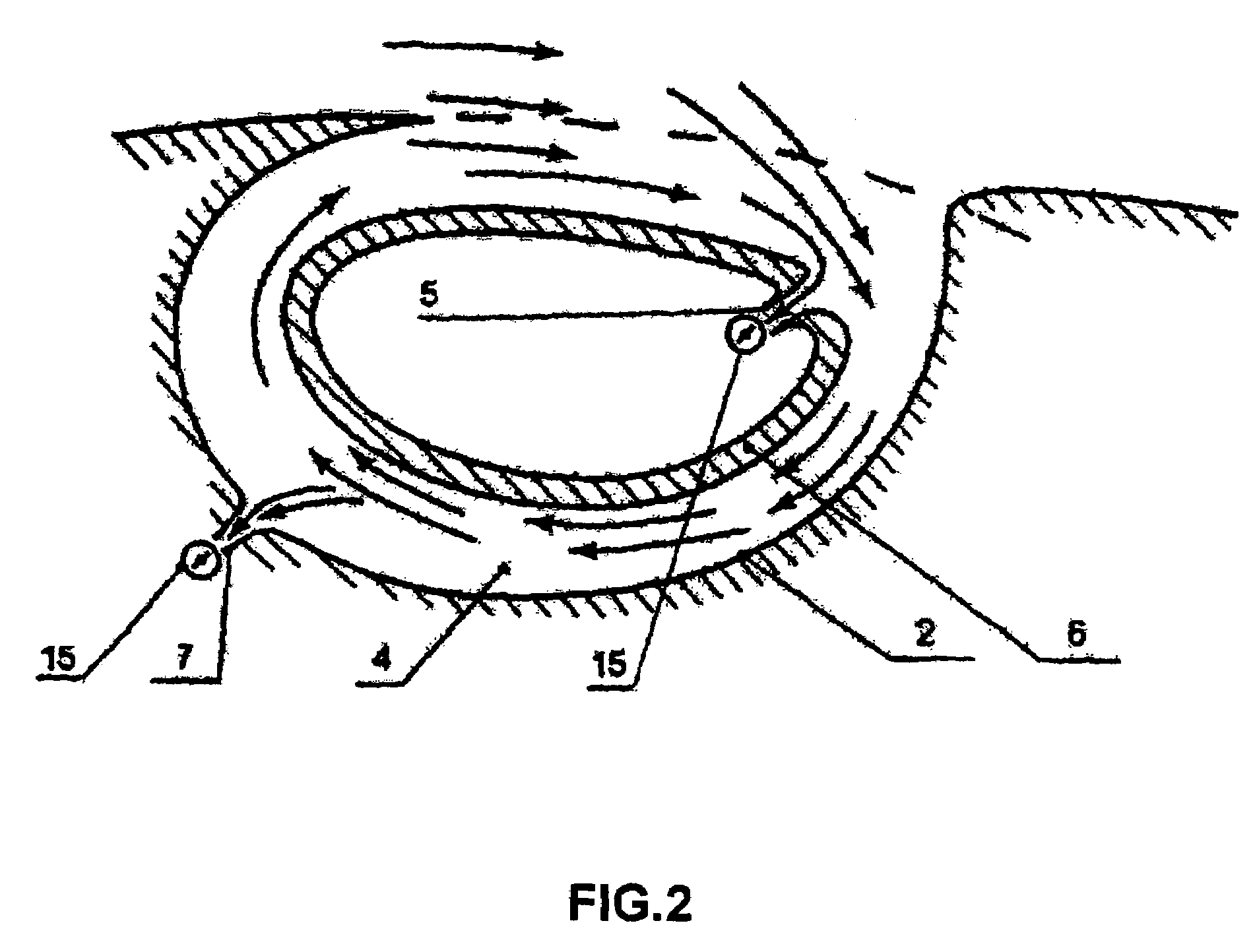
[0015]In realization of the claimed method, blade 1 of a rotor of a wind energy device is made in the form of a wing with a thick aerodynamic profile (not shown) and a vortex system for control of the boundary layer is arranged on the rear part of the blade 1 at the side away from the wind, this system consisting of longitudinal cavities 2 with central bodies 6 forming annular channels 4 and air is suction withdrawn from each cavity 2 and each central body 6 through profiled air vents 7 and 5 into receivers 3 and 9, which are connected by air ducts 11 and 12 to a low pressure receiver 10 inside the blade 1, wherein the annular channel 4 has a wider portion in the front part.

[0016]The hollows of each of the cavities 2 is coupled to the receivers 3 with the aid of air vents 7, and the cavities of each of the central bodies 6 with the aid of air vents 5 to the receivers 9. Coupling the receivers 3 and 9 to the receiver 10 provides for dosage of the suction withdrawal of air from the ca...


PUM


Abstract

A method for enhancing effectiveness of a rotor blade of a wind energy device (a wind-wheel of electric generating unit), according to which a rotor blade is implemented in the form of a thick-airfoil wing, and a vortex system for controlling the boundary layer is arranged on the rear portion of the blade, upon the leeward, which system consists of longitudinal cavities having central bodies that define annular channels; the air being sucked from the cavities and central bodies through air-intakes into receivers. The air from the receivers, under the action of centrifugal forces generated by the rotating blade, is sucked towards the blade end. Within the cavities and on the blade's outer surface are positioned the plates that restrict streaming-down of the air flow along the blade.

Description

[0001]This application is a National Stage application of co-pending PCT application PCT / RU03 / 00526 filed Nov. 26, 2003, which was published in US under PCT Article 21(2) on Jul. 15, 2004, which claims the benefit of the RU Application No. 2002135386 filed Dec. 30, 2002. These applications are incorporated herein by reference in their entireties.FIELD OF THE INVENTION[0002]The invention relates to wind energy, in particular to wind energy devices (WED) converting wind energy into electrical, mechanical, hydraulic or other form of energy.BACKGROUND OF THE INVENTION[0003]A device for controlling the boundary layer is known, in which a method of enhancing the effectiveness of controlling the boundary layer on an aerodynamic surface (for example, on the surface of a rotor blade of a wind energy device) is realized by suction withdrawal of air from the rear wall of the cavity in combination with tangential blowing into an annular channel (see patent RU 2032595, IPC B 64 C 21 / 08, 10 Apr. ...

Claims


Application Information

Patent Timeline
Patent Type & Authority Patents(United States)
IPC IPC(8): B64C11/16F03D5/00B64C21/08F03D1/06
CPCF03D1/0608F05B2240/30Y02E10/721Y02E10/72
Inventor SHCHUKIN, ILIYA LVOVICHSHCHUKIN, ANDREJ LVOVICHZELVINSKIJ, SEMEN MIKHAJLOVICHLIPNITSKIJ, JURIJ MIKHAJLOVICHISAEV, SERGEJ ALEKSANDROVICH
Owner LNS WINDBLADE TECH LLC
Features
  • R&D
  • Intellectual Property
  • Life Sciences
  • Materials
  • Tech Scout
  • Unparalleled Data Quality
  • Higher Quality Content
  • 60% Fewer Hallucinations
Learn More