Hydrogen sensor, hydrogen sensor device and method of detecting hydrogen concentration

a technology of hydrogen sensor and hydrogen concentration, applied in the field of hydrogen sensor, can solve the problems of not being developed, optical sensors are suitable for precise analysis, and the hydrogen selectivity of hydrogen sensors is not excellent, and achieves good hydrogen selectivity and responsiveness in detection, and high concentration region

Inactive Publication Date: 2007-06-26
PANASONIC CORP
View PDF9 Cites 22 Cited by
  • Summary
  • Abstract
  • Description
  • Claims
  • Application Information

AI Technical Summary

Benefits of technology

[0012]Therefore, with the foregoing in mind, it is an object of the present invention to provide an inexpensive hydrogen sensor that has good hydrogen selectivity and responsiveness in detection and can detect hydrogen in a high concentration region.

Problems solved by technology

However, inexpensive hydrogen sensors that have excellent hydrogen selectivity and can measure hydrogen even in a high concentration region have not been developed.
For example, optical sensors are suitable for precise analysis, but they are expensive.
Although catalytic combustion sensors and semiconductor sensors are comparatively inexpensive and have high reliability during measurement for a long time, they have poor hydrogen selectivity because they react with a reducing gas such as CO that is not an immediate subject for measurement, so that they are not suitable for detection of a high concentration of % order.
Furthermore, in semiconductor sensors, the hydrogen selectivity is increased by mixing a semiconductor material used with a catalytically active material, but they are not suitable for measurements for high concentration regions.
), and the detection precision of hydrogen concentrations is low.
Mechanical type sensors utilizing pressure variation and MOS capacitor sensors have poor responsiveness to detection, and low practical values.
In particular, inexpensive hydrogen sensors that have excellent hydrogen selectivity and good responsiveness and can detect hydrogen in a high concentration region in a simple manner are desired as a sensor for controlling a fuel battery and equipment utilizing hydrogen, but as described above, hydrogen sensors that satisfy these requirements sufficiently have not been obtained yet.

Method used


Image

  • Hydrogen sensor, hydrogen sensor device and method of detecting hydrogen concentration
  • Hydrogen sensor, hydrogen sensor device and method of detecting hydrogen concentration
  • Hydrogen sensor, hydrogen sensor device and method of detecting hydrogen concentration

Examples


embodiment 1

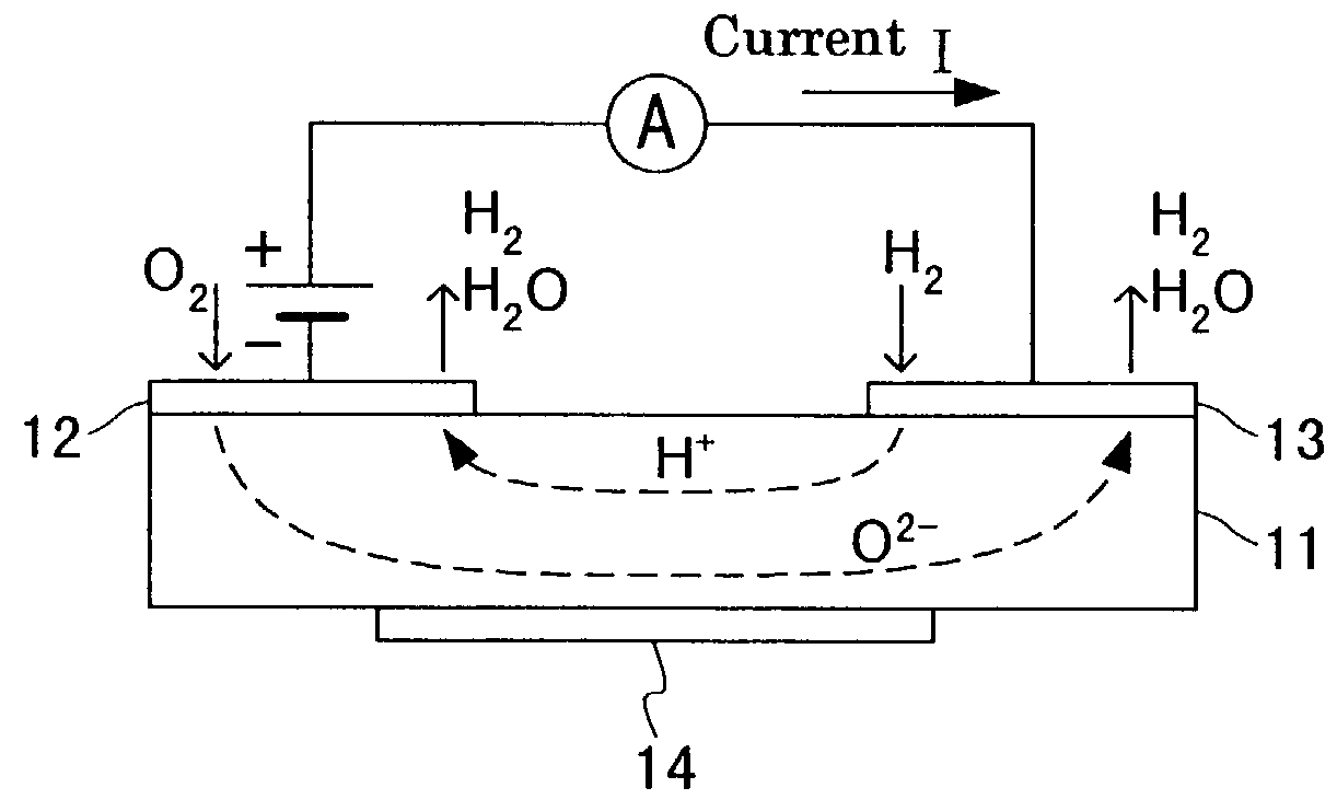
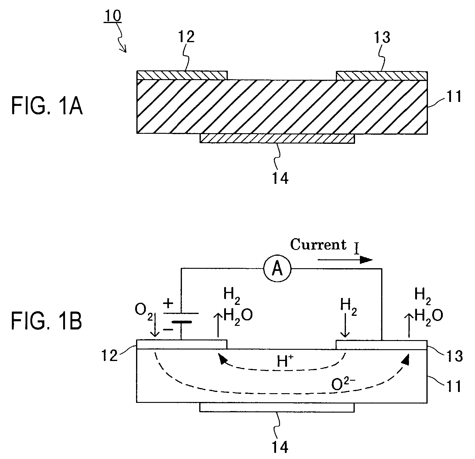
[0048]FIG. 1A shows a cross-sectional view of the structure of a hydrogen sensor 10 of this embodiment, and FIG. 1B is a schematic view showing the operation operation thereof. A solid electrolyte 11 is made of an ion conductor that conducts protons (H+) and oxide ions (O2−). A first electrode 12 and a second electrode 13 are formed on the surface of the solid electrolyte 11 to conduct ions in the solid electrolyte 11, and a heater 14 for heating the solid electrolyte 11 is provided on the lower surface thereof The heater 14 can be made of sintered platinum that has been patterned, for example.

[0049]The hydrogen sensor 10 is a so-called a current detection type sensor, and a constant voltage is applied between the first electrode 12 and the second electrode 13 so that a current generated by the conduction of oxide ions flows steadily between the first electrode 12 and the second electrode 13, and a current generated by protons is added thereto, and a current value that has changed i...

embodiment 2

[0061]FIG. 5A shows a cross-sectional view of the structure of a hydrogen sensor 20 of this embodiment, and FIG. 5B is a schematic view showing the operation thereof A solid electrolyte 11 is made of an ion conductor that conducts protons (H+) and oxide ions (O2−). A first electrode 21 and a second electrode 22 are formed on the surface of the solid electrolyte 11 to conduct ions in the solid electrolyte 11, and a heater 14 for heating the solid electrolyte 11 is provided on the lower surface thereof. The heater 14 can be made of sintered platinum that has been patterned, for example.

[0062]The hydrogen sensor 20 is a so-called a current detection type sensor like the hydrogen sensor 10 in Embodiment 1. For the solid electrolyte 11, oxides containing barium and cerium, for example, barium-cerium oxides can be used, which is the same as the hydrogen sensor 10 in Embodiment 1.

[0063]The first electrode 21 is made of a material being capable of preventing oxygen from being ionized. More ...

embodiment 3

[0072]FIG. 7A shows a cross-sectional view of the structure of a hydrogen sensor 30 of this embodiment, and FIG. 7B is a schematic view showing the operation thereof. A solid electrolyte 11 is made of an ion conductor that conducts protons (H+) and oxide ions (O2−). A first electrode 31 and a second electrode 32 are formed on the surface of the solid electrolyte 11 to conduct ions in the solid electrolyte 11, and a heater 14 for heating the solid electrolyte 11 is provided on the lower surface thereof. The heater 14 can be made of sintered platinum that has been patterned, for example.

[0073]The hydrogen sensor 30 is a so-called electromotive force type sensor, and the electromotive force between the first electrode 31 and the second electrode 32 is measured to detect the hydrogen concentration of a gas to be measured. For the solid electrolyte 11, oxides containing barium and cerium, for example, barium-cerium oxides can be used, which is the same as the hydrogen sensors in Embodime...


PUM

PropertyMeasurementUnit
temperatureaaaaaaaaaa
proton conductivityaaaaaaaaaa
temperatureaaaaaaaaaa

Abstract

A hydrogen sensor includes a solid electrolyte made of a barium cerium oxide, and a first electrode and a second electrode that are formed on the surface of the solid electrolyte. The first and the second electrodes are made of a material having a catalytic effect with respect to an oxidation reaction of hydrogen and are made of the same material. Thus, the hydrogen sensor can be inexpensive and has good hydrogen selectivity and responsiveness to detection, and thus it is possible to measure hydrogen in a high concentration region.

Description

BACKGROUND OF THE INVENTION[0001]1. Field of the Invention[0002]The present invention relates to a hydrogen sensor.[0003]2. Description of the Related Art[0004]To detect hydrogen with a high sensitivity, sensors of various systems such as optical sensors, catalytic combustion sensors, semiconductor sensors, electromotive force type sensors, current detection (battery) sensors, mechanical type sensors utilizing pressure variation that employ hydrogen adsorption or hydrogen occlusion characteristics, and MOS capacitor sensors have been developed and used in different applications in which the characteristics of each system can be exhibited sufficiently. For example, to detect gas leakage, semiconductor sensors made of a material such as TiO2, SnO2 or the like generally are used. For gas leakage of industrial or combustion equipment or temperature control, catalytic combustion sensors generally are used.[0005]In recent years, hydrogen sensors made of, for example, SrCeYO3, which is a p...

Claims


Application Information

Patent Timeline
Patent Type & Authority Patents(United States)
IPC IPC(8): G01N27/407G01N33/00
CPCG01N27/4074G01N33/005
Inventor TANIGUCHI, NOBORU
Owner PANASONIC CORP
Why Eureka
Try Eureka