Electronically tunable combine filter with asymmetric response

Inactive Publication Date: 2007-06-26
NXP USA INC
View PDF32 Cites 5 Cited by
  • Summary
  • Abstract
  • Description
  • Claims
  • Application Information

AI Technical Summary

Problems solved by technology

Mechanically tunable filters suffer f

Method used


Image

  • Electronically tunable combine filter with asymmetric response
  • Electronically tunable combine filter with asymmetric response
  • Electronically tunable combine filter with asymmetric response

Examples


Embodiment Construction

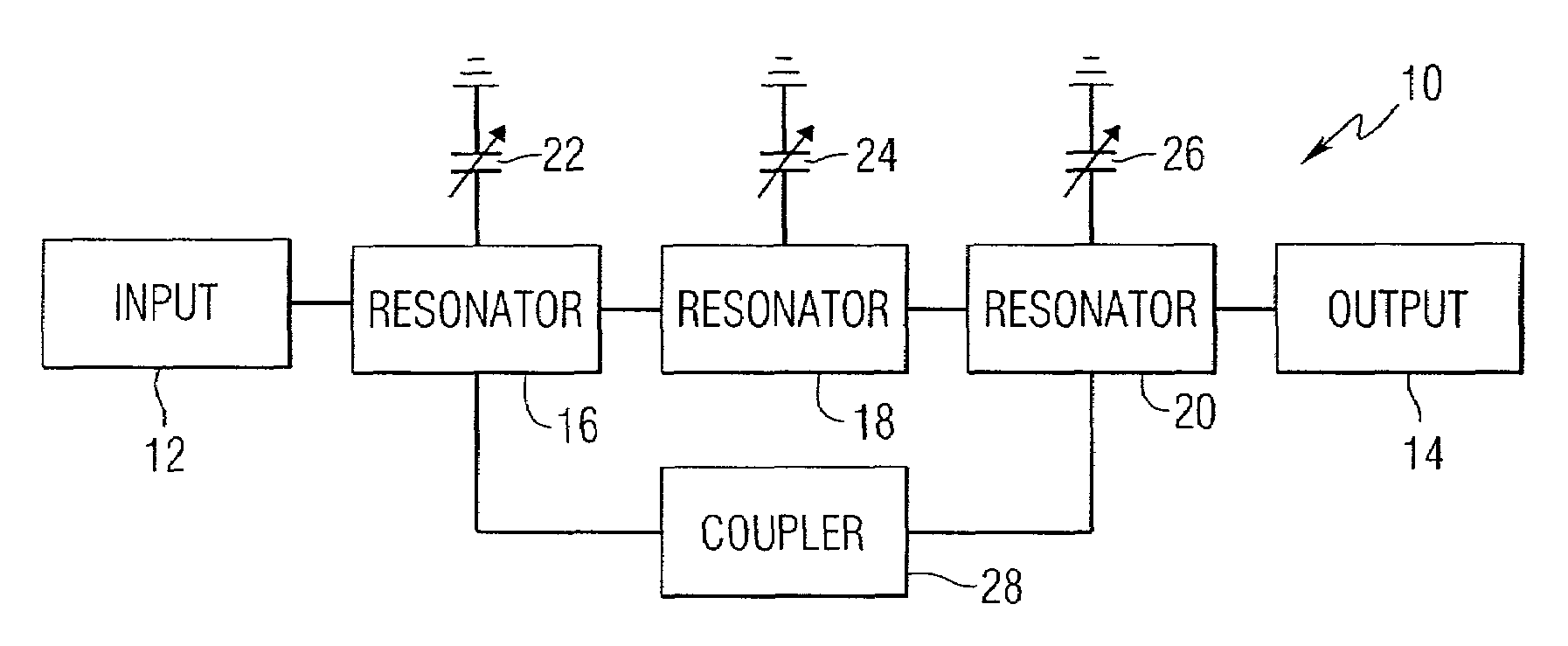
[0026]This invention provides tunable filters with an asymmetric frequency response that include cross coupling between two non-adjacent resonators to provide a transmission zero on one side of the passband of the filter. Referring to the drawings, FIG. 1 is a block diagram of a filter 10 constructed in accordance with the invention. The filter 10 includes an input 12 and an output 14. A plurality of resonators 16, 18, and 20 are serially coupled to each other and to the input and output. Tunable capacitors 22, 24 and 26 are coupled to the resonators. A coupling means 28 couples non-adjacent resonators 16 and 20.

[0027]Various structures can be used to construct the filter, such as microstrips, striplines, coaxial lines, dielectric resonator, waveguides, etc. While the example filter of FIG. 1 includes three resonators, it should be understood that additional series coupled resonators can be used in the filters of this invention. Additional cross couplings can be provided between any...


PUM


Abstract

Electronic filters include an input, an output and a plurality of resonators series coupled between the input and the output. Each of the resonators is coupled to a tunable capacitance. In addition, a coupling means is provided between non-adjacent ones of the resonators. The resonators can include microstrip resonators, stripline resonators, resonant cavities, or other types of resonators. The tunable capacitance can be provided by tunable dielectric varactors or microelectromechanical variable capacitors. Another tunable capacitor can be included in the coupling means to provide a tunable notch response.

Description

FIELD OF INVENTION[0001]The present invention relates generally to electronic filters, and more particularly, to tunable filters that operate at microwave and radio frequency frequencies.BACKGROUND OF INVENTION[0002]Wireless communications applications have increased to crowd the available spectrum and drive the need for high isolation between adjacent bands. Portability requirements of mobile communications additionally require a reduction in the size of communications equipment. Filters used in communications devices have been required to provide improved performance using smaller sized components. Efforts have been made to develop new types of resonators, new coupling structures, and new configurations to address these requirements.[0003]Electrically tunable microwave filters have many applications in microwave systems. These applications include local multipoint distribution service (LMDS), personal communication systems (PCS), frequency hopping radio, satellite communications, ...

Claims


Application Information

Patent Timeline
IPC IPC(8): H01P3/08H01P1/203
CPCH01P1/20336H01P1/20381
Inventor SHAMSAIFAR, KHOSROENIOLA, HENRY
Owner NXP USA INC
Why Eureka
Try Eureka