Power electronics component

a technology of electronics components and components, applied in the direction of printed circuit stress/warp reduction, electrical apparatus construction details, stacked and attached pcbs, etc., can solve the problems of substrate damage, electrical power components that cannot be removed, electrical power components that cannot be replaced,

Inactive Publication Date: 2007-06-26
CONTINENTAL AUTOMOTIVE GMBH
View PDF20 Cites 6 Cited by
  • Summary
  • Abstract
  • Description
  • Claims
  • Application Information

AI Technical Summary

Benefits of technology

[0007]The object of the invention is therefore to provide a power electronics unit of the type stated at the beginning which ensures good heat removal of the heat generated by the el...

Problems solved by technology

With power electronics units there is the problem that the electrical power components generate heat, which has to be removed.
On account of the different coefficients of expansion of the support element and the ceramic substrate, these components...

Method used


Image

  • Power electronics component
  • Power electronics component

Examples


Embodiment Construction

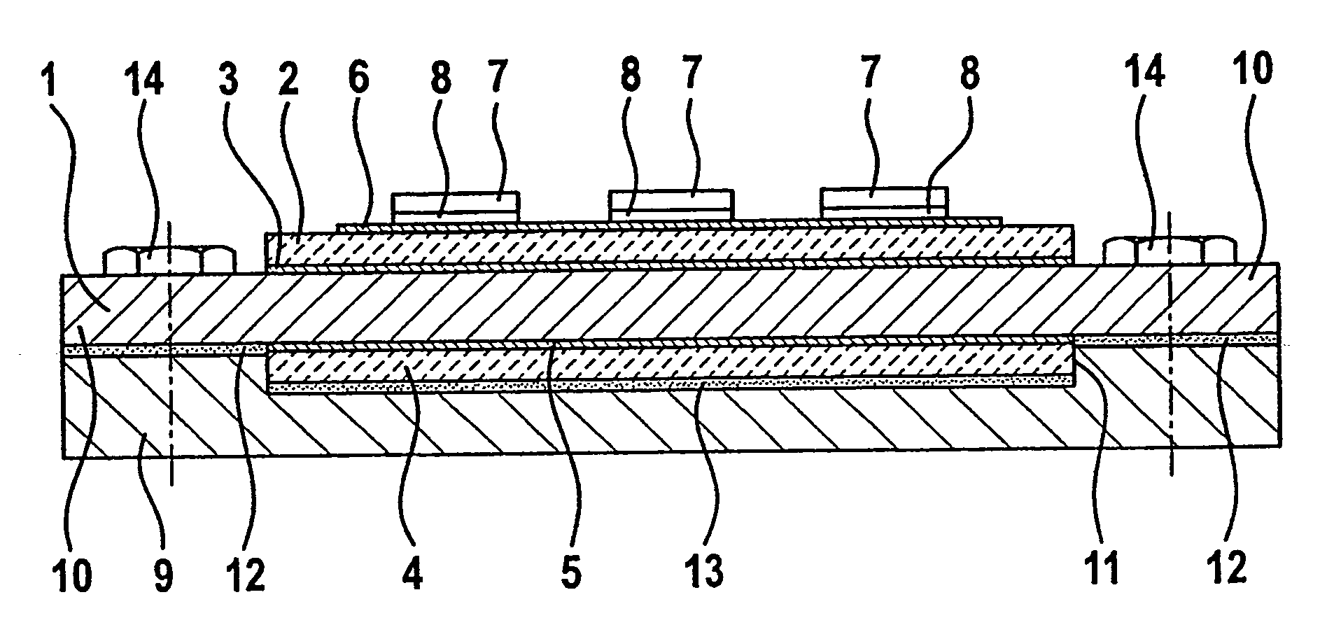
[0025]The power electronics unit represented has a rectangular support element 1 made of pure aluminum, on the upper side of which a first planar ceramic substrate 2 is brazed by a layer of hard solder 3, which covers the entire portion of the surface area of the first planar ceramic substrate 2 that faces the support element 1. On the underside of the support element 1, opposite from the ceramic substrate 2 and having the same dimensions, a second ceramic substrate 4 is likewise brazed by means of a layer of hard solder 5.

[0026]After these two brazing operations, carried out without interim cooling, a thick-film technique was used to provide the ceramic substrate 2 with conductor tracks 6, which serve for electrically connecting electrical power components 7, in this case transistors, and form a circuit with them. The electrical power components 7 are connected in a conducting manner to the conductor track 6 by means of soft solder 8, and are consequently fastened on the ceramic su...


PUM


Abstract

The invention relates to a power electronics component that comprises a planar ceramics substrate (2) on whose one face condutor tracks (6), applied in thick-film technique, are disposed for electrically connecting electrical power components (7) of a circuit that are also disposed on the ceramics substrate (2). The ceramics substrate (2), with its other face, is brazed onto a metal a metal support element (1) that serves as a heat spreader. The support element (1) is linked with a thermoconducting housing part housing that accommodates the support element (1) in a thermoconductive manner. On the face of the support element (1) facing away from the ceramics substrate (2), approximately opposite the ceramics substrate (2), a second ceramics substrate (4) is brazed onto the ceramics substrate (2) that carries the circuit and has approximately the same dimensions.

Description

PRIORITY CLAIM[0001]This is a U.S. national stage of application No. PCT / DE02 / 03 178, filed on 29 Aug. 2002. Priority is claimed on that application and on the following application(s): Country: Germany, Application No.: 101 42 615.1, Filed: 31 Aug. 2001.BACKGROUND OF THE INVENTION[0002]1. Field of the Invention[0003]The invention relates to a power electronics unit, in particular for a control device in a motor vehicle, with a planar ceramic substrate, on one side of which conductor tracks are provided using the thick-film technique for electrically connecting electrical power components of a circuit that are likewise arranged on the ceramic substrate and which is brazed by its other side onto a metal support element serving as a heat spreader, the support element being connected in a thermally conducting manner to a thermally conducting housing component of a housing accommodating the support element.[0004]2. Description of the Prior Art[0005]With power electronics units there is ...

Claims


Application Information

Patent Timeline
IPC IPC(8): H05K7/20H01L23/34H01L23/36H01L23/373H01L25/07H05K1/02H05K1/03H05K3/00
CPCH01L23/3735H05K1/0271H01L25/072H05K1/0306H05K3/0061H05K2201/043H01L2224/32225H05K2203/1572H01L2224/291H01L2924/014
Inventor LUCKE, OLAFTHYZEL, BERND
Owner CONTINENTAL AUTOMOTIVE GMBH
Why Eureka
Try Eureka