Torsion spring force and vertical shear pin retention of heat sink to CPU

a technology of heat sink and heat source, which is applied in the direction of snap fasteners, electrical apparatus construction details, buckles, etc., can solve the problems of reducing the thermal resistance between the heat sink and the heat source, severe damage to the electrical components of the computer, and occupying critical space within the confines of the computer chassis

Inactive Publication Date: 2007-06-26
IBM CORP
View PDF17 Cites 16 Cited by
  • Summary
  • Abstract
  • Description
  • Claims
  • Application Information

AI Technical Summary

Benefits of technology

[0008]The present invention addresses the deficiencies of the art with respect to heat sink retention assemblies and provides a novel and non-obvious apparatus and method for securing a heat sink to the chassis of a computer while maintaining thermal contact between the heat sink and the CPU. In this regard, a mechanical retention assembly is provided and actuated by the user. The assembly, upon actuation, advantageously prevents the heat sink from separating from the CPU, affixes the heat sink to the chassis of the computer, removes the load from the CPU, and provides mechanical support and stability to the heat sink.

Problems solved by technology

The heat generated by continued and extended use of a computer can severely damage the electrical components in the computer.
However, the problem that arises when large heat sinks or heat sinks with a large number of fins are used is that critical space within the confines of the computer chassis is used up.
This reduces the thermal resistance between the heat sink and the heat source.
Mechanical clips may help maintain the requisite pressure between the surface of the heat sink and the CPU, but such clips are usually difficult to install and are not reliable when the computer is being shipped.
Even a slight jarring during shipping may cause the weight of the heat sink to fall directly on the CPU or motherboard causing severe damage.
Further, because of the increased thickness in motherboards, the use of an under-the-board spring to dampen the force exhibited by the heat sink on the CPU and other electrical components is no longer feasible.
The recent proliferation of Land Grid Array (LGA) sockets have created another problem that must be considered during heat sink design and particularly in the manner in which heat sinks or other cooling devices are attached to the socket / CPU assembly.
Even these simple attachment means can consume a significant portion of the effective heat sink volume, since the screws or spring-loaded fasteners protrude through the heat sink and require removal or partial removal of some of the fin structure, thereby reducing its thermal efficiency.
Additionally, deflection that might occur under actuation load can create gaps between the heat sink and the assembly that can compromise the thermal effectiveness of the heat sink and / or cause the weight of the heat sink to fall directly on the CPU.

Method used


Image

  • Torsion spring force and vertical shear pin retention of heat sink to CPU
  • Torsion spring force and vertical shear pin retention of heat sink to CPU
  • Torsion spring force and vertical shear pin retention of heat sink to CPU

Examples


Embodiment Construction

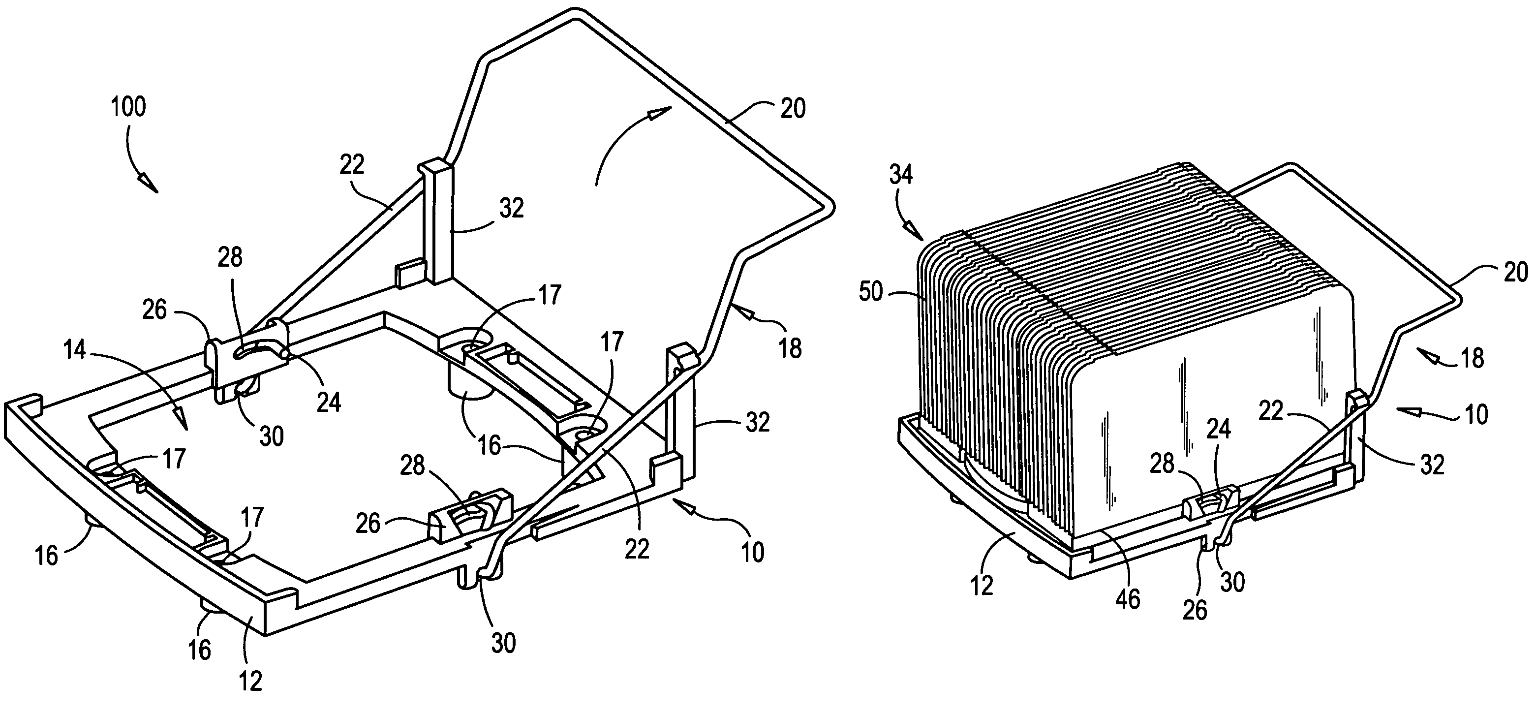
[0021]The present invention advantageously provides a method and apparatus for mounting a heat sink above an electrical component in a computer, such as a CPU, such that the heat sink is in thermal contact with the CPU but the weight of the heat sink is absorbed by the computer chassis or CPU mounting plate and not the CPU. When used with Land Grid Array (LGA) CPU technology, the present invention advantageously provides an apparatus that secures the heat sink to the motherboard or CPU of the computer and prevents unwanted separation between the heat sink and the CPU which might occur due to the solder connection between the CPU and its socket.

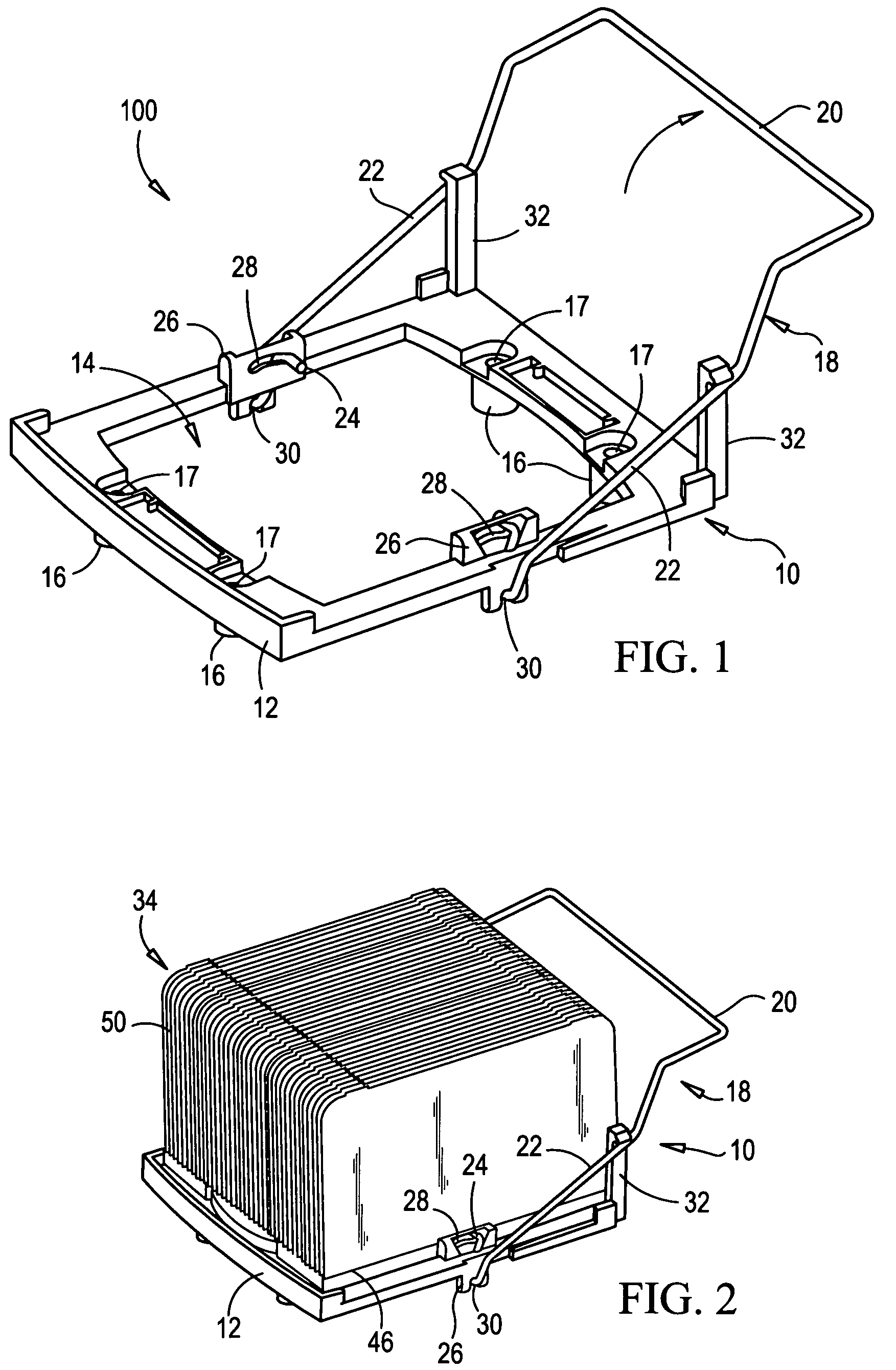
[0022]Referring now to the drawing figures in which like reference designators refer to like elements there is shown in FIG. 1 an apparatus constructed in accordance with the principles of the present invention and designated generally as “100”. Apparatus 100 includes a retention module assembly 10, which is adapted for placement on top of a m...


PUM


Abstract

A heat sink retention assembly for retaining a heat sink in thermal contact with a CPU while transmitting load away from the CPU. The heat sink retention assembly includes a frame sized to receive the heat sink, the frame including opposing pin capture channels and a wire module. The wire module includes an upper handle section and a lower pivoting section. The wire module is pivotably coupled to the frame at the lower pivoting section. The wire module further includes opposing end pins, wherein each pin is moveably retained within and extends through a corresponding pin capture channel such that when the wire module is rotated with respect to the frame, the pins travel within their respective channels in order to engage the heat sink.

Description

BACKGROUND OF THE INVENTION[0001]1. Statement of the Technical Field[0002]The present invention relates to heat sinks and more particularly to a method and apparatus of securing a heat sink above a central processing unit (CPU) of a computer in order to divert the weight and force of the heat sink to the computer's chassis or mounting plate rather than toward the CPU while maintaining the requisite thermal interface with the CPU.[0003]2. Description of the Related Art[0004]Heat sinks are a vital part of any computer system. The heat generated by continued and extended use of a computer can severely damage the electrical components in the computer. Heat sinks provide a way for the heat to be transferred away from the source and away from critical components. To increase the amount of thermal transfer, heat sinks typically include a large surface area or a large number of thermally conductive fins. However, the problem that arises when large heat sinks or heat sinks with a large numbe...

Claims


Application Information

Patent Timeline
Patent Type & Authority Patents(United States)
IPC IPC(8): H05K7/20
CPCH01L23/4093H01L2924/0002Y10T24/44026Y10T24/44496H01L2924/00
Inventor BARINA, RICHARD M.FRENCH, MICHAEL D.HERRING, DEAN F.SCAVUZZO, JOHN P.WORMSBECHER, PAUL A.
Owner IBM CORP
Why Eureka
Try Eureka