DC/AC converter and its controller IC

a dc/ac converter and controller technology, applied in the direction of electric variable regulation, process and machine control, instruments, etc., can solve the problems of low power inversion efficiency, inability to maintain a constant output voltage, and inability to easily miniaturize the inverter utilizing the royer circui

Active Publication Date: 2007-06-26
ROHM CO LTD
View PDF6 Cites 13 Cited by
  • Summary
  • Abstract
  • Description
  • Claims
  • Application Information

AI Technical Summary

Benefits of technology

[0050]In an inverter and a controller therefor for supplying controlled constant voltage and current to a load through PWM control thereof, the invention enables use of a common slow-start circuit in the inverter and the controller IC to suppress an excessive load voltage and an excessive load current during a startup of the load. Thus, the invention facilitates extension of the life of CCFL and relieves stresses on the constituent elements such as a transformer, a semiconductor switch circuit, and batteries.
[0051]The first error signal associated with the output current and the second error signal associated with the output voltage are integrated into a common error signal. The feedback loops, which feed back the common error signal as a feedback voltage, may be unified. Particularly, when the controller IC utilizes external feedback elements, feedback terminals for the external elements can be reduced in number.
[0052]The slow-start circuit may be adapted to cooperate with an external capacitor, external to the IC, for generating a slow-start voltage, so that the rising time of the slow-start circuit can be properly optimized by adjusting the capacitance of the external capacitor in accordance with the characteristics of the load.

Problems solved by technology

However, a Royer circuit is basically a constant-voltage inverter, which cannot maintain a constant output voltage if the input voltage thereto and / or the load current thereof varies.
For this reason, the inverter utilizing a Royer circuit cannot be easily miniaturized, and has low power inversion efficiency.
Although conventional inverters are designed to drive a load under a constant-current control and protect the load against an excessive voltage, it is often the case that the load, particularly a CCFL in the present example, is subjected to an excessive current and / or excessive voltage during a startup on account of a loop-delay encountered in the constant-current control or an operational delay in protection against an excessive voltage.
This excessive current and excessive voltage impose a strong stress on the CCFL, thereby shortening the life of the CCFL.

Method used


Image

  • DC/AC converter and its controller IC
  • DC/AC converter and its controller IC
  • DC/AC converter and its controller IC

Examples


Embodiment Construction

[0055]The invention will now be described in detail by way of example with reference to the accompanying drawings illustrating an inverter for generating an ac voltage to drive a load from a dc power supply, and a controller IC therefor.

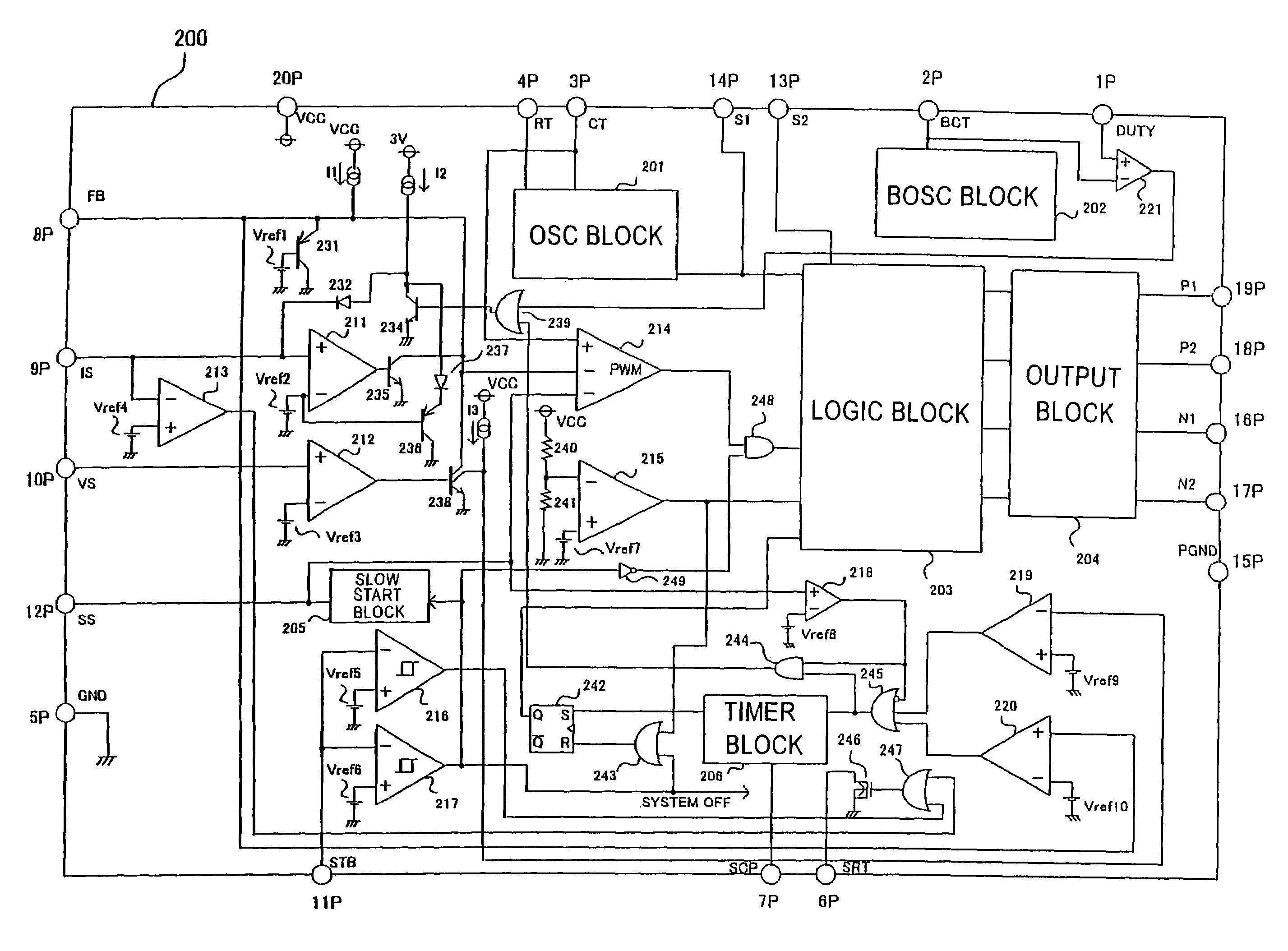
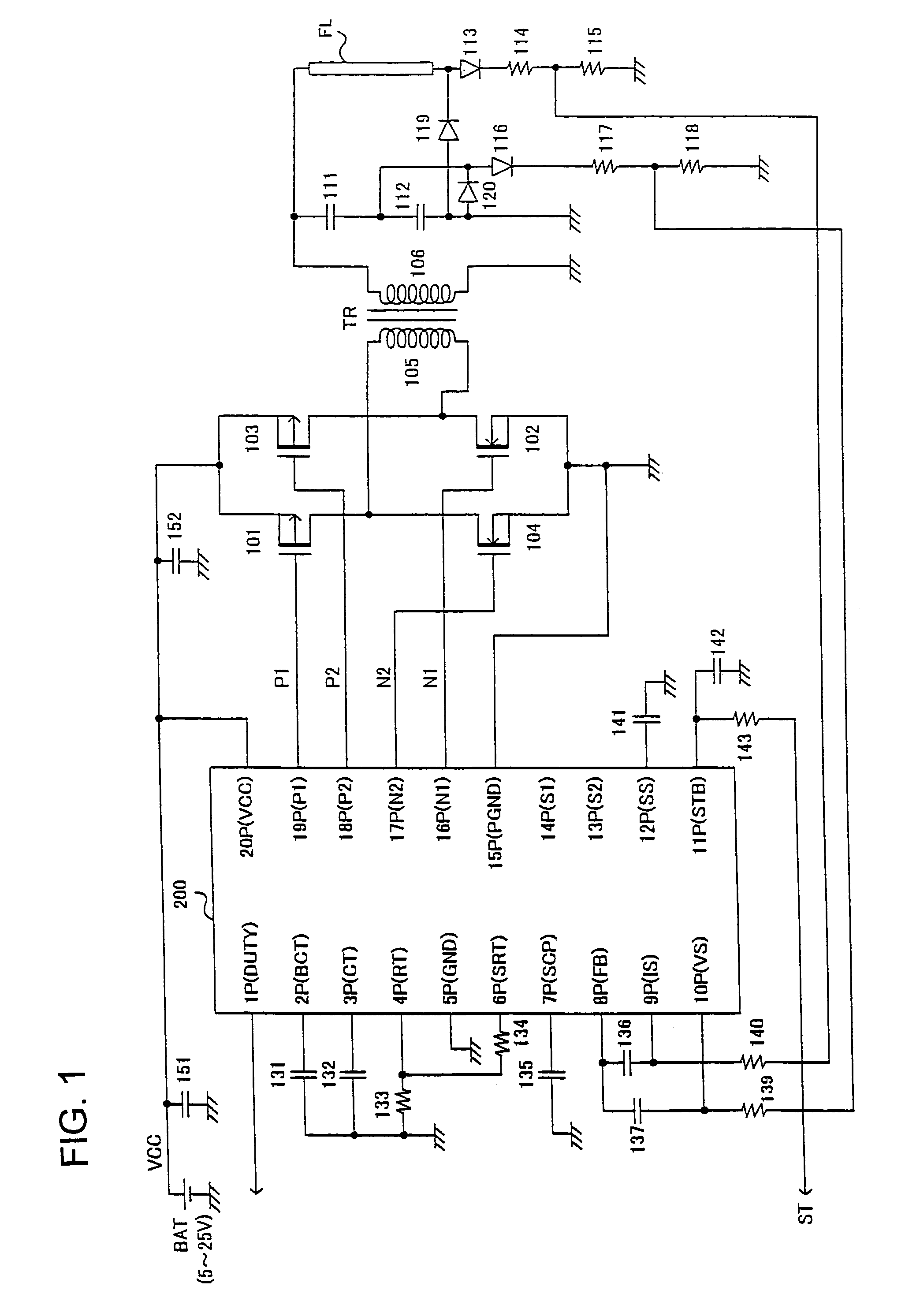
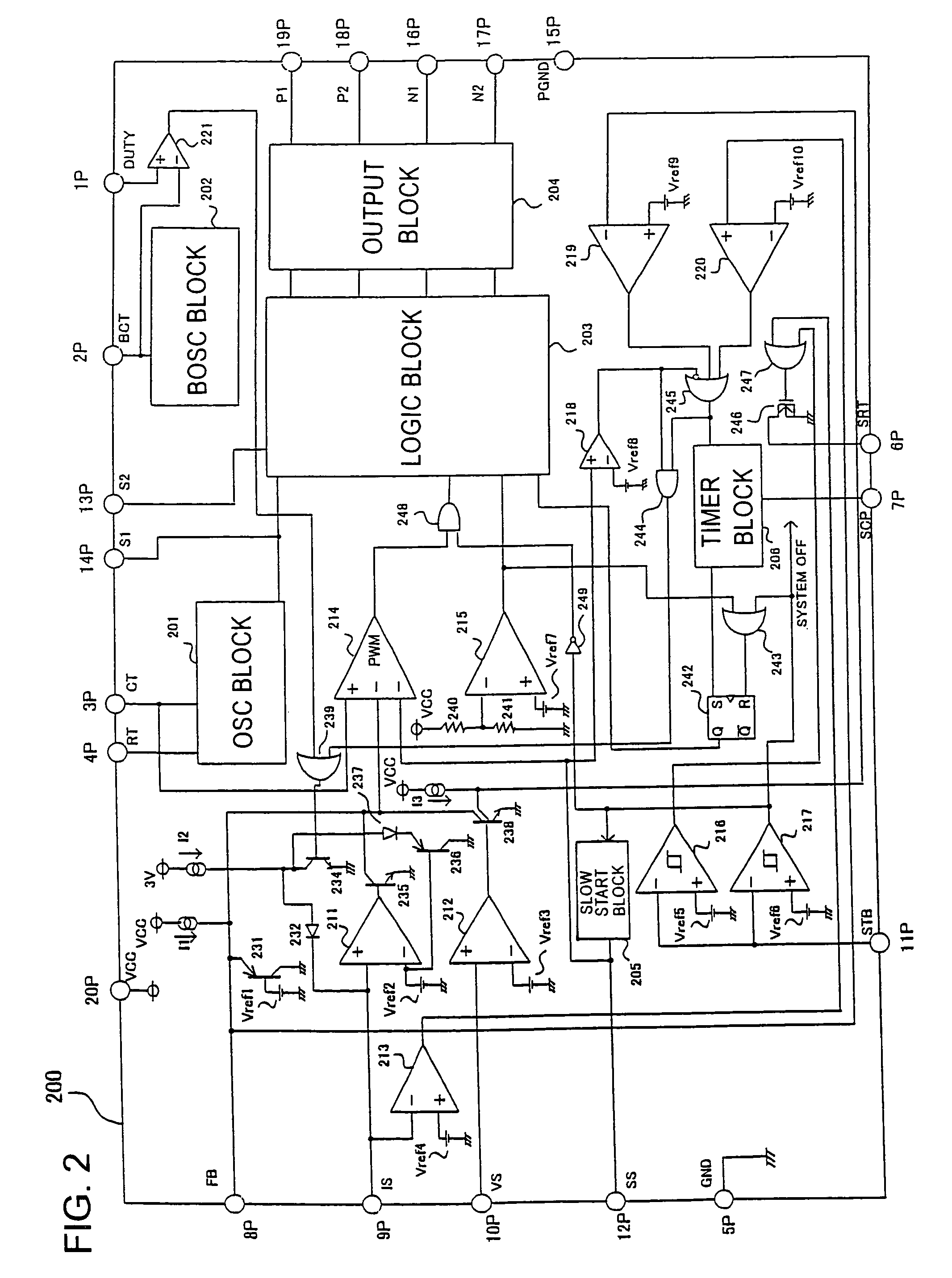
[0056]Referring to FIG. 1, there is shown an over-all arrangement of an inverter according to the invention that utilizes an insulated transformer and a full-bridge switch circuit for carrying out PWM control. FIG. 2 illustrates the internal structure of a controller IC (i.e. IC for controlling inverter) for use in the inverter of FIG. 1.

[0057]As shown in FIG. 1, a first switch in the form of a P-type MOSFET (hereinafter referred to as PMOS) 101 and a second switch in the form of an N-type MOSFET (hereinafter referred to as NMOS) 102 constitute a first current path in a first direction from a dc power supply to the primary winding 105 of a transformer TR. A third switch in the form of a PMOS 103 and a fourth switch in the form of NMOS 104 constitute ...


PUM


Abstract

An inverter has a semiconductor switch circuit in the primary winding of a transformer such that each of the switches of the switch circuit is controlled by pulse-width modulation (PWM) to supply a constant ac current and a constant ac voltage to a load, such as a cold cathode fluorescent light, connected to a secondary winding of the transformer. A common slow-start control circuit is provided in the inverter circuit to enable a common slow startup of the PWM control of the output voltage and output current. This arrangement suppresses an excessive voltage and an inrushing current during a startup.

Description

TECHNICAL FIELD[0001]This invention relates to a dc-ac converter (hereinafter referred to as inverter) for generating ac power to drive a load, from a dc power supply unit such as a power supply adapter of an electric apparatus and a battery. The invention also relates to a controller IC for use in such inverter.BACKGROUND OF THE INVENTION[0002]A cold cathode fluorescent light (CCFL) has been increasingly used as a back light source of a liquid crystal display monitor of a notebook PC and of a liquid crystal display (LCD) for use with, for example, a TV set. Such CCFL has substantially the same high efficiency and long life as a usual hot cathode fluorescent light, without using a filament of the hot cathode fluorescent light.[0003]In order to start up and operate the CCFL, a high ac voltage is required. For example, a startup voltage of about 1000 V and an operating voltage of about 600 V are required. These high ac voltages are generated from a dc power supply unit of, for example...

Claims


Application Information

Patent Timeline
Patent Type & Authority Patents(United States)
IPC IPC(8): H02M3/00H02M7/00H05B41/36H05B41/24H02M3/28H02M7/48H05B41/282
CPCH02M1/36H05B41/2828H02M7/53871Y02B20/186Y02B20/00H02M7/48H02M7/527
Inventor FUKUMOTO, KENICHIFUJITA, HIROYUKI
Owner ROHM CO LTD
Why Eureka
Try Eureka