Tunable dispersion compensation apparatus

a compensation apparatus and dispersion technology, applied in the direction of instruments, optical elements, optics, etc., can solve the problems of limited operation speed of electrical signals processing portions, high capacity, and inability to fully exploit the high-speed advantages of optical signals, so as to reduce the effects of transmission channel dispersion, increase the compensation amount, and widen the range of variability

Inactive Publication Date: 2007-06-26
NAT INST OF INFORMATION & COMM TECH
View PDF4 Cites 2 Cited by
  • Summary
  • Abstract
  • Description
  • Claims
  • Application Information

AI Technical Summary

Benefits of technology

[0020]With the tunable dispersion compensation apparatus according to this invention, when optical signals used in high-speed communications are transmitted across long distances among various points, it is possible to suppress the effects of the transmission channel dispersion which impedes transmission based on information about the intervals among those various points, thus permitting even higher-speed optical communications.
[0021]In addition, with the tunable dispersion compensation apparatus according to this invention, by utilizing the effect of the dispersion arising in the FBG, making the FBG tunable and changing the number of laps of circulation by means of an optical SSB modulator, the range of variability is made wider and the amount of compensation is increased.

Problems solved by technology

However with this method, the operating speed of the portions that process electrical signals is limited, so there is a problem in that the high capacity, high-speed advantages of optical signals cannot be fully exploited.
However, there are drawbacks in that optical amplifiers are required to compensate for the losses in delay lines that use large numbers of optical fibers, and the structure becomes complicated.
When long-distance, high-speed transmission is performed, waveform deterioration typically occurs due to the effect of dispersion within the optical fiber.

Method used


Image

  • Tunable dispersion compensation apparatus
  • Tunable dispersion compensation apparatus
  • Tunable dispersion compensation apparatus

Examples


embodiment 1

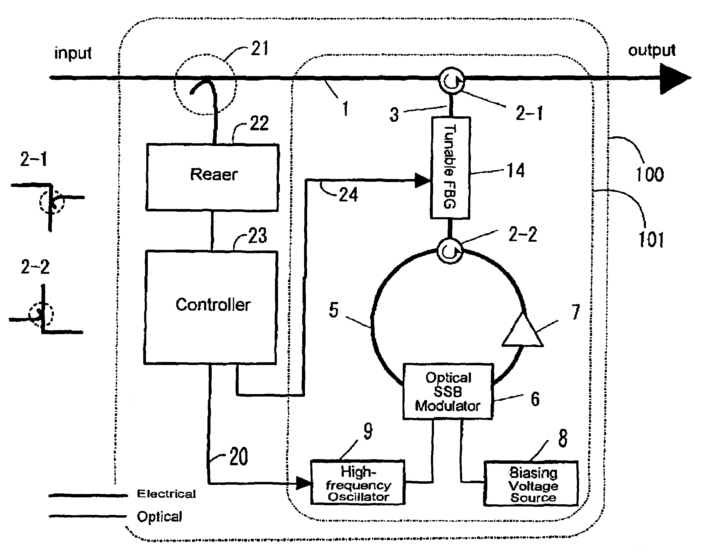
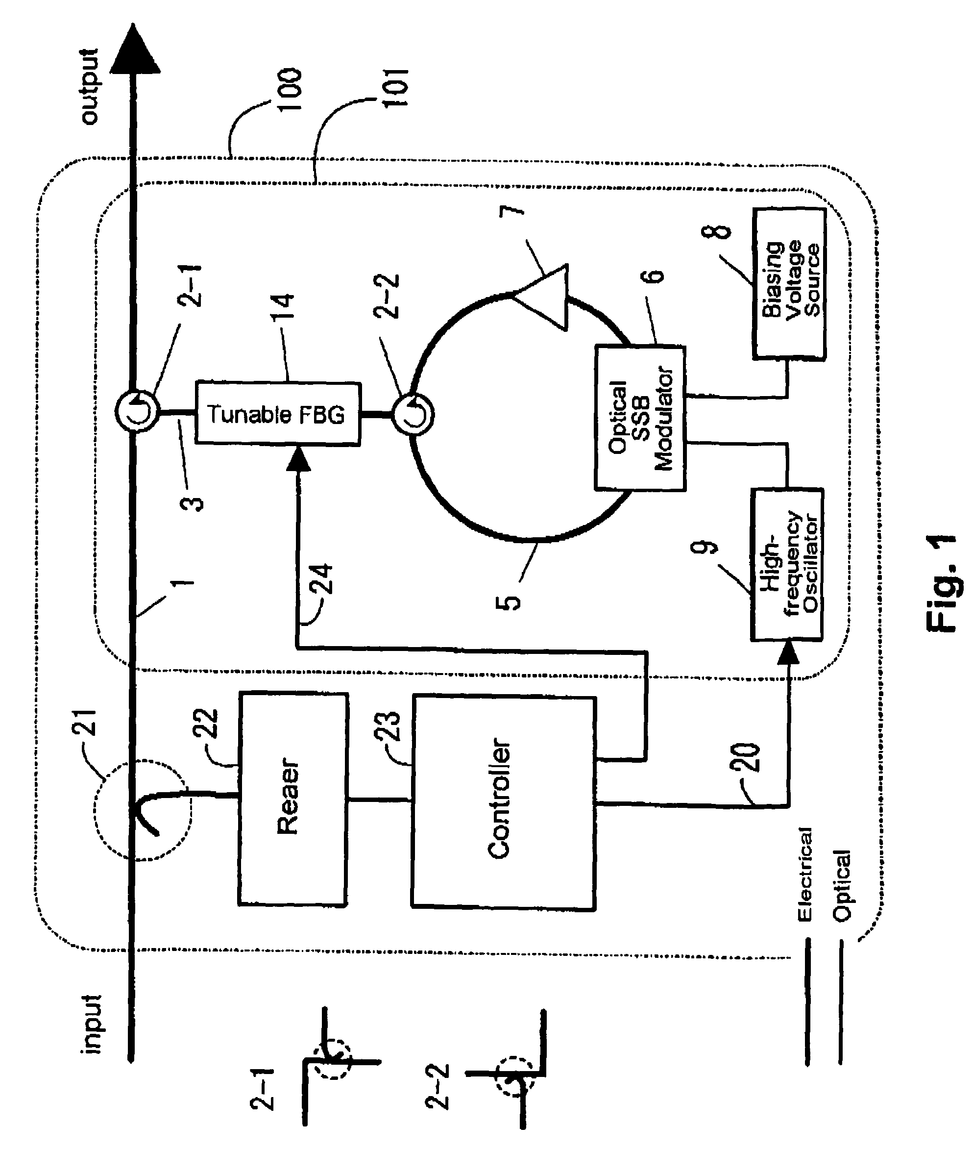
[0038]FIG. 1 is a block diagram illustrating, as Embodiment 1 of the invention, a tunable dispersion compensation apparatus 100 that compensates after receiving signals. This is an apparatus that performs dispersion compensation on received optical signals based on information that accompanies the received optical signal, being provided with an input block and output block for the received optical signal. In addition a dispersion compensation block 101 is provided between the input and output blocks, and the compensation of wavelength dispersion is performed here. The operation of this dispersion compensation block 101 can be replaced with that of the dispersion compensation block 201 to be described later.

[0039]In the dispersion compensation block 101, a dispersion element that has wavelength dispersion characteristics, consisting of tunable FBG 14, and a wavelength shifter that is able to adjust the amount of shift depending on the input optical signal, consisting of an optical SS...

embodiment 2

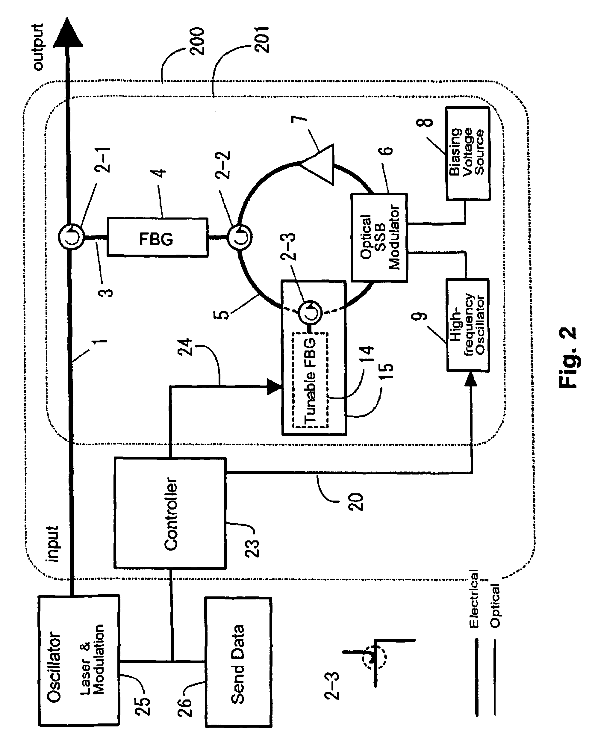
[0042]In addition, FIG. 2 is a block diagram illustrating, as Embodiment 2 of the present invention, a tunable dispersion compensation apparatus 200 that compensates for the wavelength dispersion of the transmission channel prior to the transmission of an optical signal. This is an apparatus that performs dispersion compensation in advance on optical signals to be sent based on address information in the optical signal to be sent, being provided with an input block and output block for the optical signal to undergo dispersion compensation in advance. In addition, a dispersion compensation block 201 is provided between the input and output blocks, and the compensation of wavelength dispersion is performed here. The operation of this dispersion compensation block 201 can be replaced with that of the dispersion compensation block 101 described above. In addition a transmission-type tunable dispersion element is used as the tunable dispersion element 15, but one using a circulator 2-3 a...

embodiment 3

[0047 will be described. With the tunable dispersion compensation apparatus shown in FIG. 1 or FIG. 2, the frequency of the output optical signal is shifted from that at the time of input. There are cases in which such frequency shifts are preferably as small as possible. In the constitution shown in FIG. 4, the dispersion compensation block is divided in two, giving a constitution wherein the frequency shifts cancel each other out. Here, a tunable FBG is provided in each of the dispersion compensation blocks, but it may be provided in only one. In addition, the frequencies of the modulation signals applied to each of the optical SSB modulators need not necessarily be the same.

[0048]With the tunable dispersion compensation apparatus of FIG. 1 or FIG. 2 above, one tunable FBG is used for dispersion compensation, but a pair of tunable FBGs may also be used instead. The optical circuit shown in FIG. 5(a) is an example wherein the dispersion compensation block consists of an optical fil...


PUM

PropertyMeasurementUnit
wavelength dispersionaaaaaaaaaa
wavelengthaaaaaaaaaa
dispersion characteristicsaaaaaaaaaa

Abstract

This invention is a tunable dispersion compensation apparatus that suppresses the effects of the transmission channel dispersion which impedes transmission when optical signals used in high-speed communications are transmitted across long distances among various points. It is an apparatus that performs dispersion compensation upon received optical signals based on information that accompanies the received optical signals, or an apparatus that performs dispersion compensation in advance upon optical signals to be sent based on information related to the destination of the optical signals to be sent, including: an input block and output block for optical signals, with a dispersion element that has wavelength dispersion characteristics and a wavelength shifter that is able to adjust the amount of shift depending on the input optical signal provided in a circulating light path upon the light path from the input block to the output block, and further including a constitution whereby the input optical signal circulates around a circulating light path containing the dispersion element and wavelength shifter a stipulated number of times before reaching the output block, and a constitution whereby the number of times the light circulates is determined based on the information and input to the wavelength shifter.

Description

BACKGROUND OF THE INVENTION[0001]1. Field of the Invention[0002]This invention relates to a tunable dispersion compensation apparatus that suppresses the effects of the transmission channel dispersion which impedes transmission when optical signals used in high-speed communications are transmitted across long distances among various points.[0003]2. Description of the Prior Art[0004]In data communications systems for the Internet and mobile telephones, packet-switched systems are used instead of the circuit-switched systems used in conventional fixed voice telephony. In packet-switched systems, it is necessary to adjust the timing of the large numbers of packets arriving at a switch so that they do not collide with each other, and transmit the packet signals to their respective destinations. In the case of high-speed systems that use optical fiber for transmission in particular, in existing packet-switched systems, the optical signals are first converted to electrical signals and sto...

Claims


Application Information

Patent Timeline
Patent Type & Authority Patents(United States)
IPC IPC(8): G02B6/26H04B10/00G02F1/01G02B6/34G02F2/02H04B10/2507H04B10/2519H04B10/524
CPCG02B6/2932G02B6/29322G02B6/29394G02B6/29395H04B10/25133G02B6/29398
Inventor KAWANISHI, TETSUYAIZUTSU, MASAYUKISET, SZE YUNJABLONSKI, MARK KENNETHTANAKA, YUUICHI
Owner NAT INST OF INFORMATION & COMM TECH
Why Eureka
Try Eureka