Internal combustion engine for a motor vehicle

a technology for internal combustion engines and motor vehicles, which is applied in the direction of machines/engines, mechanical equipment, cylinders, etc., can solve the problems of reducing the speed of friction losses after a cold start, and achieve the effect of increasing the flow of coolant, reducing friction losses, and heating up the internal combustion engine very quickly

Inactive Publication Date: 2007-07-03
DAIMLER AG
View PDF7 Cites 41 Cited by
  • Summary
  • Abstract
  • Description
  • Claims
  • Application Information

AI Technical Summary

Benefits of technology

[0006]The internal combustion engine according to the invention is distinguished by a main coolant pump which can be switched on and off. In order to ensure rapid heating of the cylinder head in a warming up phase, the coolant is not circulated in the internal combustion engine, i.e. the coolant in the engine block and in the cylinder head is stationary. The pump wheel of the main coolant pump is not driven. The engine oil is heated quickly, as a result of which its viscosity drops and the piston friction is reduced.
[0013]In a further embodiment of the invention, a differential pressure valve is arranged between the second control unit and the main coolant pump. The differential pressure valve opens starting at a certain pressure and clears a line to the main coolant pump. Below this pressure, for example at low engine speeds, coolant therefore does not flow back through the small coolant circuit, i.e. the coolant preferably flows back to the coolant pump via the heating circuit. If the circulation of coolant is to take place at low temperatures exclusively via the additional coolant pump, the differential pressure valve prevents coolant from flowing back to the second control unit and prevents the coolant from flowing back to the intake duct of the additional coolant pump by bypassing the cylinder head and / or the engine block. The differential pressure valve thus comprises two functions, a priority circuit for the heating circuit and a return flow inhibitor. If the priority circuit function for the heating circuit is not needed, it is of course possible to use a simple non-return valve in its place.
[0014]In still a further embodiment of the invention, a heat exchanger for exhaust gas recirculation, passenger heating and / or engine oil is arranged in the heating circuit line. On the one hand, the recirculated exhaust gas flows through the heat exchanger for the exhaust gas recirculation and on the other hand coolant flows through the heat exchanger, as a result of which the exhaust gas is cooled before it is returned to the combustion chamber. The cooling of the recirculated exhaust gas reduces the proportion of nitrogen oxide in the emissions of the internal combustion engine. The heat exchanger for passenger compartment heating includes flow passages for the coolant and flow passages for the air, said air being heated in the heat exchanger and thus heating the passenger compartment. The heating capacity is regulated either by controlling the flow of coolant or the flow of air through the heat exchanger. A heat exchanger through which both engine oil and coolant flow is also provided for cooling the engine oil.
[0016]In another embodiment of the invention, the heat exchanger for the passenger compartment and for the engine oil is arranged in the heating circuit line, and the heat exchanger for the exhaust gas recirculation is arranged in a coolant line which branches off downstream of the coolant pump and upstream of the inflow port of the cylinder head and opens into a return flow line of the internal combustion engine. The arrangement of the heat exchanger for the passenger heating upstream of the engine oil heat exchanger is advantageous since at first the passenger compartment is supplied with heat and less heat is transferred to the engine oil. The heat exchanger for the exhaust gas recirculation is supplied with cooled engine inlet water when there is a flow through the air / fluid cooler.

Problems solved by technology

Since the cooling fluid in the engine block is not circulated until the operating temperature is reached it can heat up very quickly, as a result of which the frictional losses which occur after a cold start decrease quickly.

Method used


Image

  • Internal combustion engine for a motor vehicle
  • Internal combustion engine for a motor vehicle
  • Internal combustion engine for a motor vehicle

Examples


Embodiment Construction

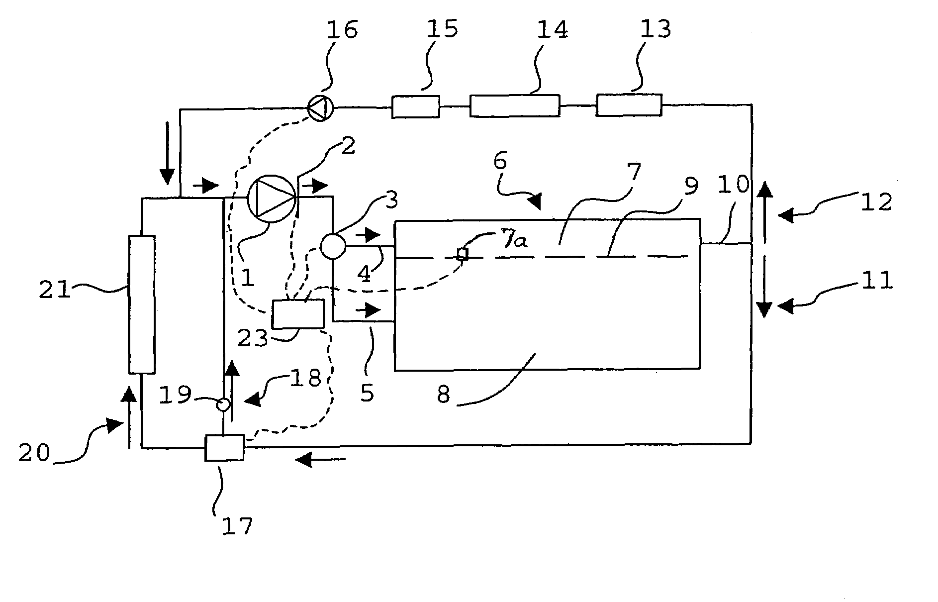
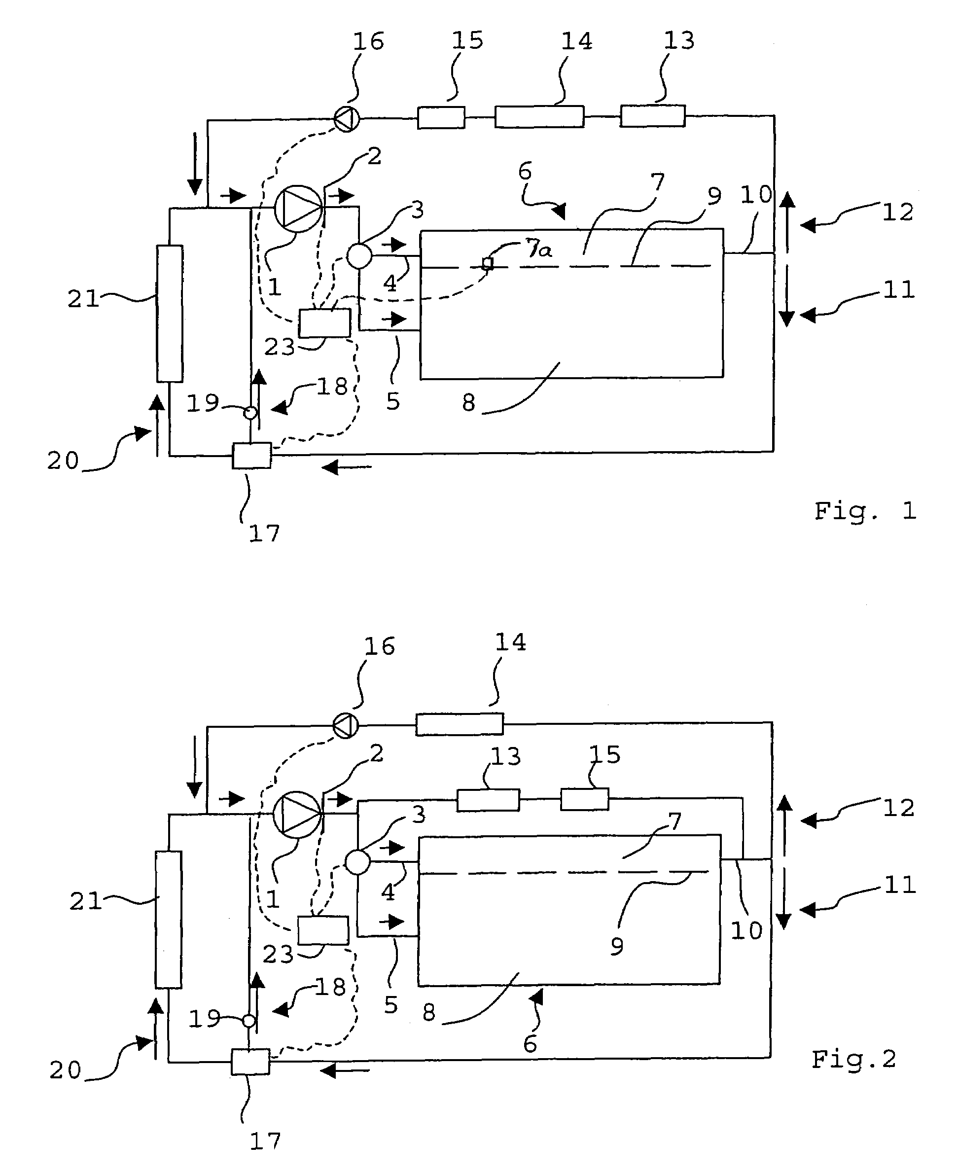
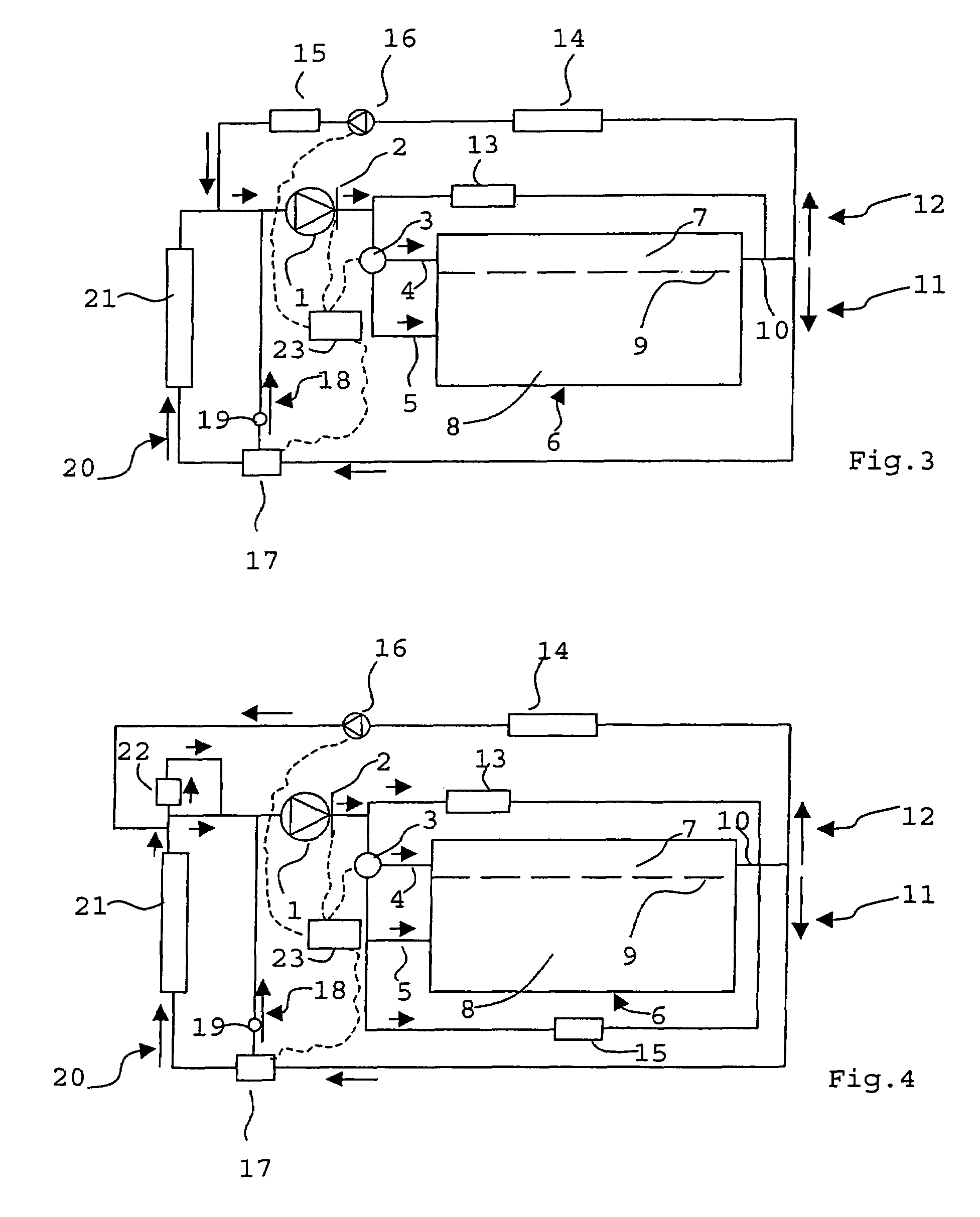
[0028]Identical parts in the FIGS. 1 to 4 are designated below by the same reference symbols.

[0029]The schematic illustration in FIG. 1 shows an internal combustion engine 6 which is provided with a cooling circuit. The direction of flow of a coolant in the cooling circuit is indicated in each case by an arrow at various points. The coolant which circulates in the cooling circuit flows from the main coolant pump 1 through the assemblies as will be described below.

[0030]The main coolant pump 1 which is operatively connected to a crank shaft (not shown) of the internal combustion engine 6 circulates the cooling fluid in the cooling circuit. In the embodiment shown, the main coolant pump 1 can be decoupled mechanically. The drive of the main coolant pump 1 is provided by means of a belt, i.e. a V-belt or toothed belt or by means of gearwheels.

[0031]By activating a clutch 2, the main coolant pump can be disconnected from the drive. The clutch 2 can be actuated electrically and can be sw...


PUM


Abstract

In an internal combustion engine for a motor vehicle, having a cylinder head and an engine block, each with a coolant inlet port and a coolant outlet port which is common to the cylinder head the engine block, a main coolant pump having an intake side connected to the coolant outlet port and a pressure side connected to a first control valve via which coolant reaches the inlet port of the cylinder head and the inlet port of the engine block depending on the temperature of the coolant, and to a method for operating such an internal combustion engine, wherein the main coolant pump is selectively actuated to pump the coolant through at least one of the cylinder head and the engine block or is shut down depending on the engine operating state.

Description

[0001]This is a Continuation-In-Part Application of International Application PCT / EP2004 / 007771 filed Jul. 14, 2004 and claiming the priority of German application 103 32 947.1 filed Jul. 19, 2003.BACKGROUND OF THE INVENTION[0002]The invention relates to an internal combustion engine for a motor vehicle having a cylinder head with coolant inlet and outlet ports and an engine block with coolant inlet and outlet ports and a coolant pump having an inlet in communication with the outlet ports of the cylinder head and the engine block and an outlet in communication with the inlet ports of the cylinder head and the engine block and also to a method of operating such an internal combustion engine.[0003]Laid-open patent application DE 28 41 555 A1 discloses an internal combustion engine which has a coolant inflow for an engine block and a coolant inflow for a cylinder head. A pump feeds coolant to a temperature-controlled valve. Depending on the design, the valve feeds coolant into the cyli...

Claims


Application Information

Patent Timeline
Patent Type & Authority Patents(United States)
IPC IPC(8): F01P3/00F01P5/10F01P3/02F01P7/14F01P7/16
CPCF01P7/162F01P7/164F01P7/165F01P2003/021F01P2003/024F01P2003/027F01P2005/105F01P2007/146F01P2025/12F01P2025/13F01P2025/33F01P2025/40F01P2025/44F01P2025/46F01P2060/04F01P2060/08
Inventor PFEFFINGER, HARALDSASS, HEIKO
Owner DAIMLER AG
Why Eureka
Try Eureka