Device for high-accuracy measurement of dimensional changes

a measurement device and high-accuracy technology, applied in the direction of measurement devices, instruments, interferometers, etc., can solve the problems of significant errors in the connection between the reference surface and the test material, the accuracy of dimensional change measurement is not high, and the thermally induced dimensional variation of the instrument (referred to as the device) is often nearly the same or even greater, so as to improve the accuracy of dimensional change measurement, improve the accuracy of estimating and compensating, and improve the accuracy of measurement accuracy

Inactive Publication Date: 2007-07-03
CORNING INC
View PDF6 Cites 13 Cited by
  • Summary
  • Abstract
  • Description
  • Claims
  • Application Information

AI Technical Summary

Benefits of technology

[0006]Our invention is intended to increase the accuracy of dimensional change measurements, such as CTE (coefficient of thermal expansion) measurements of ultra-low thermal expansion materials by better estimating and compensating for instrument and sample errors. Dimensional changes of measuring instruments that contribute to the uncertainty of measured dimensional changes of materials are themselves accurately measured and subtracted from the measured dimensional changes of the materials. With the exception of reflections from end surfaces of the measured materials, which can be accommodated in other ways, the entire measurement path of the instrument is preferably measured to better distinguish the dimensional changes of the measured materials from dimensional changes of the measuring instrument.
[0007]A preferred configuration of our new measuring instrument readily accommodates measurements of different length test materials such as ultra-low thermal expansion materials. Auxiliary optics forming joints or connections with the end surfaces or other parts of the test materials are preferably eliminated to reduce sources of error, provide increased design flexibility, and simplify a comparison between measurements of the materials and self-measurements of the new instrument. The preferred configuration is also readily adaptable to alternative configurations for making comparisons with conventional measuring protocols.
[0023]A retroreflector along with quarter-wave retarders straddling the test material can be used together with the polarizing beamsplitter to double the path lengths of the test beam portions traversing the test arm. The test material-measuring portions of the test beam reflect twice from the end surfaces of the test material, effectively doubling the measurement resolution. The quarter-wave retarders orthogonally rotate polarization during each pass (two encounters) of the test material-measuring portions of the test beam so that upon a first return, the polarizing beamsplitter directs the test material-measuring portions of the test beam to the retroreflector and upon a second return, the polarizing beamsplitter returns the test material-measuring portions to the main beam router.
[0024]The instrument-measuring portions of the test beam traverse the measuring loop twice, in opposite directions. Polarization effects of the quarter-wave retarders cancel each other; and upon retroreflection, the instrument-measuring portions of the test beam retrace their paths to the main beam router. In addition to doubling the path lengths of the test-material- and instrument-measuring portions of the test beam, the retroreflector inverts the beams. The inversion reduces sensitivity of the measurements to angular mounting variations and angular motions of the test material end surfaces and components of the measuring loop. Such odd-order differences, which can be sources of error, tend to cancel between passes.

Problems solved by technology

However, since few if any materials exhibit lower thermal expansion characteristics, the instruments (referred to as devices) used for measuring ultra-low thermal expansion materials are often subject to nearly the same or even greater thermally induced dimensional variations.
Accompanying thermal deformations of the measuring instrument are generally the largest source of uncertainty in the CTE measurements.
However, these interferometers have difficulty consistently relating the test and reference beams where the beams depart in the vicinity of the test materials under investigation.
Joints and other connections between reference surfaces and the test material are significant sources of error.
However, the instrument-measuring path does not account for all of the spurious variations undergone by the test material-measuring path.

Method used


Image

  • Device for high-accuracy measurement of dimensional changes
  • Device for high-accuracy measurement of dimensional changes
  • Device for high-accuracy measurement of dimensional changes

Examples


Embodiment Construction

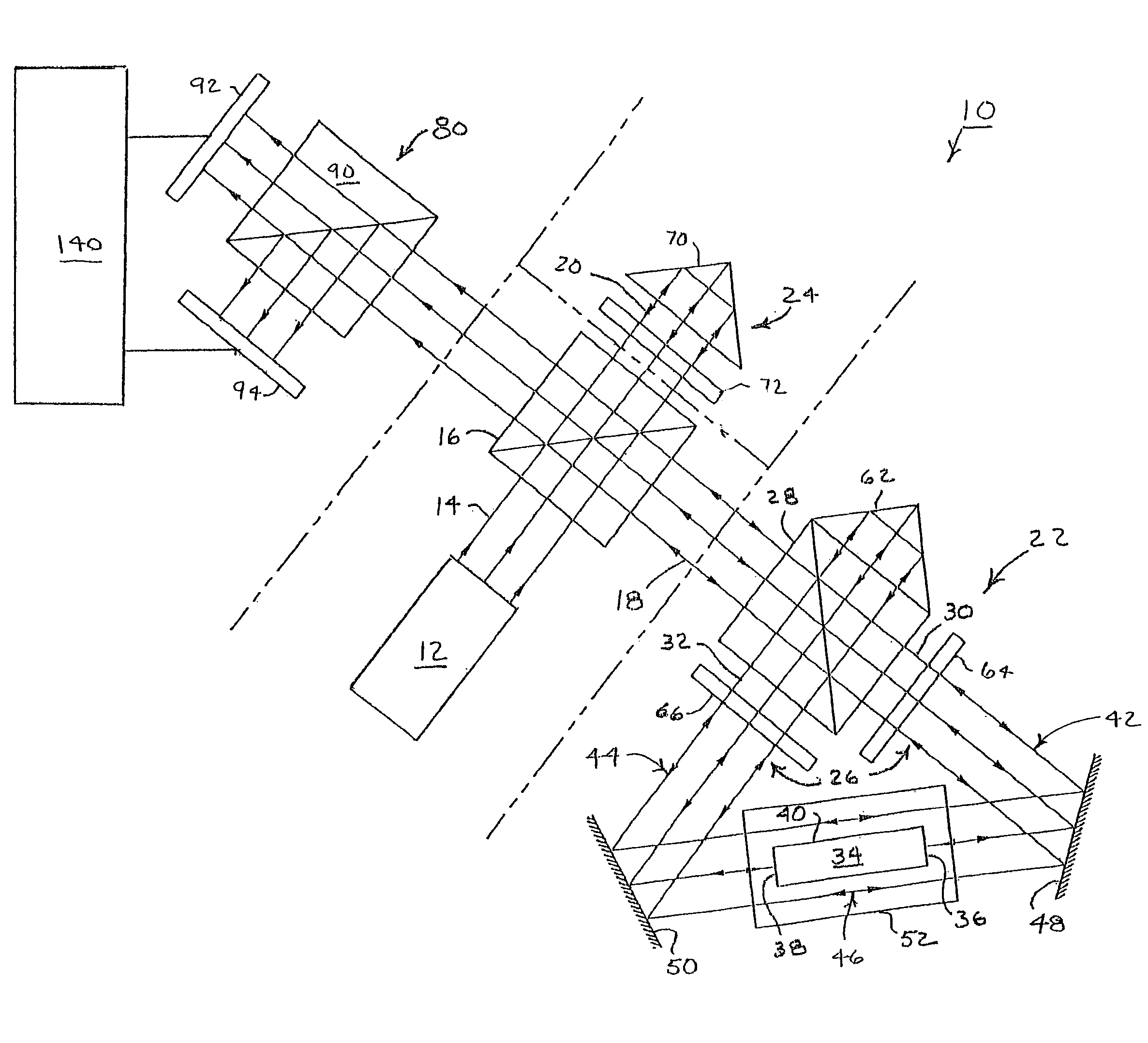
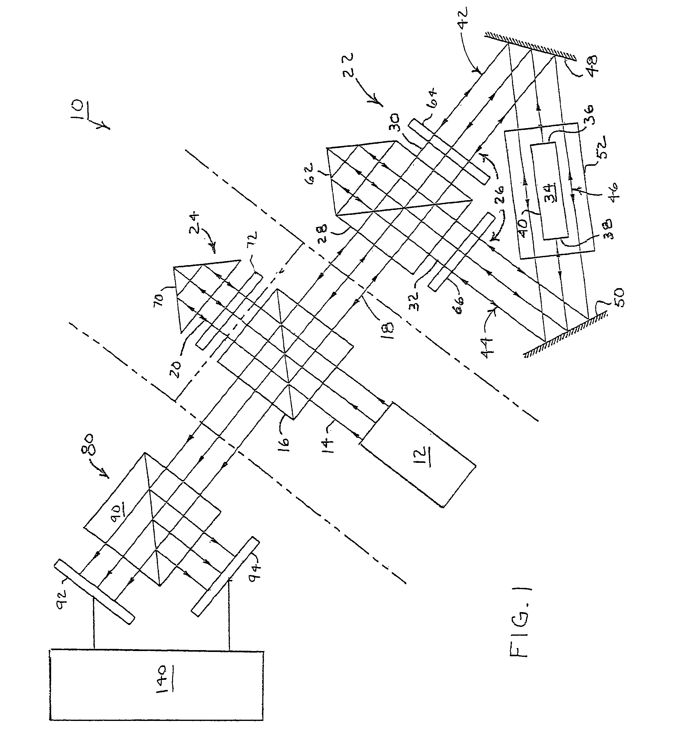
[0044]An exemplary device 10 laid out in FIG. 1 has the general configuration of a Michelson interferometer but is specially arranged for making heterodyne displacement measurements of ultra-low thermal expansion materials. Such materials generally exhibit thermal expansions of less than 30 parts per billion per degree centigrade.

[0045]A multi-frequency laser source 12 emits an expanded beam of light 14 having two primary frequencies (f1 and f2 ) that are linearly polarized in nominally orthogonal states (p and s). The laser is preferably a HeNe laser, such as a 7712 Laserhead from Zygo Corporation, emitting two primary frequencies (f1 and f2 ), which together exhibit a beat frequency of approximately 20 megahertz. Higher or lower beat frequencies can be used, since the expected rates of change intended for measurement are slow. The cost of electronic monitoring tends to decrease with lowered beat frequencies. The measurement resolution is set by the average of the two frequencies (...


PUM

PropertyMeasurementUnit
beat frequencyaaaaaaaaaa
temperatureaaaaaaaaaa

Abstract

Thermal expansion characteristics of test materials of ultra-low thermal expansion material are measured with a test beam that is split into a test material-measuring portion and an instrument-measuring portion. Both measuring portions propagate through common portions of a test arm. The test material-measuring portion encounters a test material, but the instrument-measuring portion does not. Thermal expansion characteristics of the test material are measured to high accuracy by manipulating the measures to distinguish displacements associated with the test material from displacements associated with the instrument structure.

Description

CROSS-REFERENCE TO RELATED APPLICATION[0001]This application claims the benefit of priority under 35 U.S.C. §·119(e) of U.S. Provisional Application Ser. No. 60 / 533,810 filed on Dec. 31, 2003.TECHNICAL FIELD [0002]The invention relates to precision instruments for measuring dimensional changes of materials, particularly those applied to the measurement of thermal expansion / contraction characteristics of ultra-low thermal expansion materials.BACKGROUND[0003]Ultra-low thermal expansion materials such as ULE® Glass (a trademark of Corning Incorporated) and Zerodur® (a trademark of Schott Glas) provide dimensional stability for a variety of precision applications including structures requiring significant dimensional stability over a range of temperatures. Examples include structural materials for precision machines and instruments and substrates for space optics, telescopes, and extreme ultra-violet lithography (EUVL) optics and photomasks.[0004]For such purposes as calibration, certif...

Claims


Application Information

Patent Timeline
Patent Type & Authority Patents(United States)
IPC IPC(8): G01B9/02G01B11/16G01N25/16
CPCG01B11/161G01N25/16G01B9/02003G01B9/02021G01B9/02027G01B2290/70G01B2290/45
Inventor BADAMI, VIVEK G.PATTERSON, STEVEN R.
Owner CORNING INC
Why Eureka
Try Eureka