
Eureka
For R&D, Eureka makes reading and utilizing patents & technical documents easy.
Eureka AIR
Designed for self-driven R&D workflows. Generate viable solutions, solve complex R&D challenges, empower your innovation with AI.

Eureka Materials
Designed for material experts only. Revolutionize your material R&D, from search, analyze, to developing new materials.

TechResearch
Generate reliable direction feasibility study reports for your R&D in just a few steps.

TechSeek
Discover and master advanced knowledge NOW. Basics, ideas, possibilities, all at once.

TechMind
As an expert in R&D Theories, TechMind can generates customized viable solutions instantly.

TechRisk
Analyze your overall solution with one click, know your potential R&D risks in advance.

TechMonitor
Get weekly tech updates, stay abreast of the latest tech innovations and key insights.
Lens for optical recording and reproducing system
- Summary
- Abstract
- Description
- Claims
- Application Information
AI Technical Summary
Benefits of technology
Problems solved by technology
Method used
Image

Examples
first embodiment
[0058]FIG. 4A is a sectional view showing an optical lens having an ellipsoidal side in accordance with the present invention.
[0059]As shown in FIG. 4A, the side where a focal point (P) of the lens is positioned is level with the bottom surface.
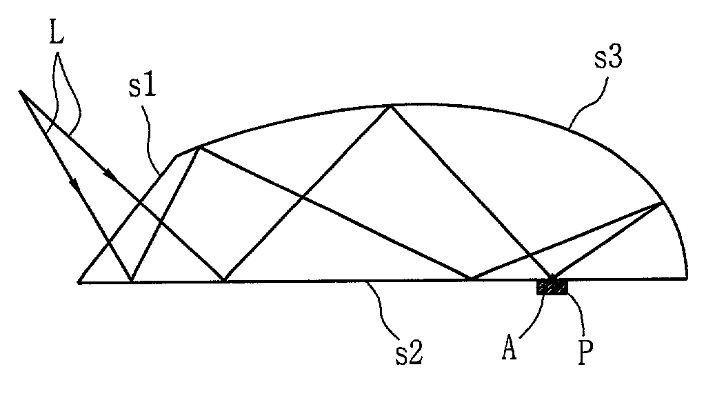
[0060]Substantially, in an optical recording system, the lens is preferably positioned at a head in this manner, because light (L) generated from a light source can be made incident horizontally on a lens incident portion.
[0061]One side of the lens is formed as a plane of incidence on which light (L) is made incident, and a lower surface of the lens is a first reflection side (s2) from which an incident light is reflected, and an upper surface of the lens corresponds to a second reflection side (s3), an ellipsoidal side.
[0062]The focal point of the ellipsoidal side is the point ‘P’ formed at one side of the first reflection side, and light made incident on the lens penetrates a point symmetrical to the other focal point of the ellipsoid and t...
second embodiment
[0067]FIG. 4B is a drawing illustrating a lens having a step (A) formed at a focal point in accordance with the present invention.
[0068]Formation of a step (A) helps to prevent a bad influence to recording and reproducing because an optical interaction takes place between a portion other than the focal point at the bottom surface of the lens and the recording medium and also prevents a contaminant from interfering an optical interaction between the lens and the recording medium.
[0069]The material to form the step should be a transparent material so as to transmit light, and the step is preferably formed to have a size of about 0.1˜100 nm, so that it may not cause a trouble to recording and reproducing of information.
[0070]By performing an aperture coating at the focal point portion, the spot size of the focussed light can be more reduced.
[0071]FIGS. 5 through 7 show different embodiments of the present invention, in which a plane of incidence of lens is formed at the same position a...
fifth embodiment
[0075]FIG. 7 is a drawing illustrating a lens having a hologram formed at a plane of incidence (s1) in accordance with the present invention.
[0076]As shown in FIG. 7, a hologram is formed at the plane of incidence (s1) of the lens.
[0077]The hologram formed at the plane of incidence allows a diffraction angle and a fracture aberration to be controllable, so that a tolerance margin can be great, and in this aspect, the hologram is advantageous.
[0078]FIG. 8 is a schematic view showing the construction of an optical recording and reproducing system having the lens in accordance with a preferred embodiment of the present invention.
[0079]The light generated from the light source 31 is converted into a parallel beam as it passes a collimation lens 32, and reaches the focussing lens 37 after passing through a beam splitter 33.
[0080]The light (36) converted to the focusing lens makes an optical magnetic interaction with the surface of the recording medium 38 being rotated by the motor 39, to...
PUM
 Abstract
Description
Claims
Application Information
 - R&D Engineer
- R&D Manager
- IP Professional
- Industry Leading Data Capabilities
- Powerful AI technology
- Patent DNA Extraction
Browse by: Latest US Patents, China's latest patents, Technical Efficacy Thesaurus, Application Domain, Technology Topic, Popular Technical Reports.
© 2024 PatSnap. All rights reserved.Legal|Privacy policy|Modern Slavery Act Transparency Statement|Sitemap|About US| Contact US: help@patsnap.com