Method, computer program product and use of a computer program for stabilizing a multiphase flow

a multi-phase flow and computer program technology, applied in the direction of process and machine control, instruments, wellbore/well accessories, etc., to achieve the effect of avoiding flow variation, improving operating conditions, and reducing feed disturbances

Inactive Publication Date: 2007-07-03
ABB (SCHWEIZ) AG
View PDF11 Cites 19 Cited by
  • Summary
  • Abstract
  • Description
  • Claims
  • Application Information

AI Technical Summary

Benefits of technology

[0040]An advantage of the present invention is that it improves the stability of operating conditions in production facilities for oil and / or gas. In particular the invention significantly reduce the disturbances in feed to the separation process by avoiding flow variation at the outlet of the multiphase flow line that connect wells and remote installation of the processing unit.
[0041]Another advantage of the invention, compared with a conventional control method, is that the invention reduces the pressure fluctuations at the flow line inlet. This stabilizes the multiphase flow line, which makes it possible not only to reduce the effects of slugging, as in the case of conventional methods, but also to entirely avoid slugging.
[0042]An advantage of the invention, compared with a conventional control method, is that it stabilizes the multiphase flow throughout the complete flow line. This also means that by applying the invention the production rate, for instance at a production platform, may be increased.
[0043]An advantage of the invention is that, compared with conventional methods, it reduces the number of occurrences and formations of slugs in a flow line. In this way the invention enables energy to be used in a more efficient way in the flow line in order to transport a multiphase mixture of oil, gas and water. This in contrast of letting energy out of the system in the form of blowouts as slugs leave the outlet of the flow line, such as the outlet of a riser.
[0044]Another advantage of the invention, compared with conventional methods using design changes, is that it does not require new process equipment to be installed. Hence, substantial capital investment is avoided. It is however assumed that there is at least one available pressure or temperature measurement along the flow line upstream the point where the main part of the slug is generated. It is also assumed there is at least one control valve in the flow line.
[0045]It is an aim of the invention to supply a method, which applies to a dynamic feedback controller, which is a multivariable input, single output controller, wherein the method acts upon periodic variations in measured variables.

Problems solved by technology

Then the whole process is repeated, and the result is an unstable multiphase flow pattern / cycle where the liquid flow rate varies from zero to a significant value, as the slug passes a fixed point in the pipeline, in a short period of time.
Unstable flow causes considerable problems for production in the upstream wells and operation of the downstream processing plant:Large disturbances to the separator train, causing:Limiting separation capacity due to the need for larger operating margin to achieve the desired separation.Poor separation (water carry over to export pipeline) due to rapidly varying separator feed rates.Poor separation results in varying quality of water outlet from separators, causing large problems in the downstream water treatment system and possible violation of environmental restrictions.Large and rapidly varying compressor loads, causing:Inefficient compressor operation.Limiting compression capacity due to the need for a larger margin to handle gas holdup behind the liquid.Spurious flaring from limited compression capacity.Limited production from the upstream wells.
The pressure variations at the pipeline or riser inlet 1 are also visible in the upstream wells, resulting in limited production from wells suffering from reduced lifting capacity.
For gas lifted oil wells a problem referred to as casing heading might occur.
Such design changes also have the disadvantage of that substantial capital investment is needed.
For already existing installations where problems with slug flow are present, and for compact separation units, these design changes have limited effects on flow stability.
Still, using this technique, compressors may trip due to large rapid variations in the feed rates to the separators caused by unstable multiphase flow.
But such an operational change may have the disadvantage of decreasing the output flow to a level substantially lower than the capacity of the pipeline.
But a problem is that the approach with rule-based calculations may only decrease the magnitude of slugging at certain operating conditions.
A remaining problem by applying conventional control methods is to stabilize the multiphase flow in a complete flow line and not only reducing the effect of slugging at a single point of the flow line, typically the outlet of the flow line.
Another problem with conventional control methods is that they have not proven to be efficient enough when it comes to stabilize multiphase flow and particularly not in flow-lines comprising remote well-head platforms and subsea wells.

Method used


Image

  • Method, computer program product and use of a computer program for stabilizing a multiphase flow
  • Method, computer program product and use of a computer program for stabilizing a multiphase flow
  • Method, computer program product and use of a computer program for stabilizing a multiphase flow

Examples


Embodiment Construction

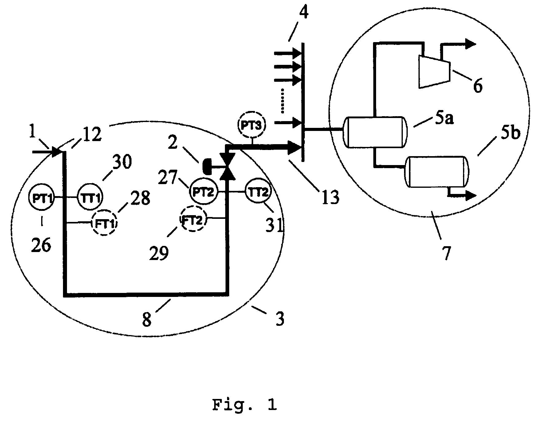
[0072]FIG. 1 shows a schematic topologic overview of a flowline control system 3 based on the invention. The figure also shows that as an example the flowline 8a could be a pipeline between a wellhead platform 1 and a production platform 7. Several flow lines 4 may operate in parallel. In the example where the flowline 8a connects to a production platform 7 the platform comprises a compressor 6 and a first 5a and second stage 5b separator.

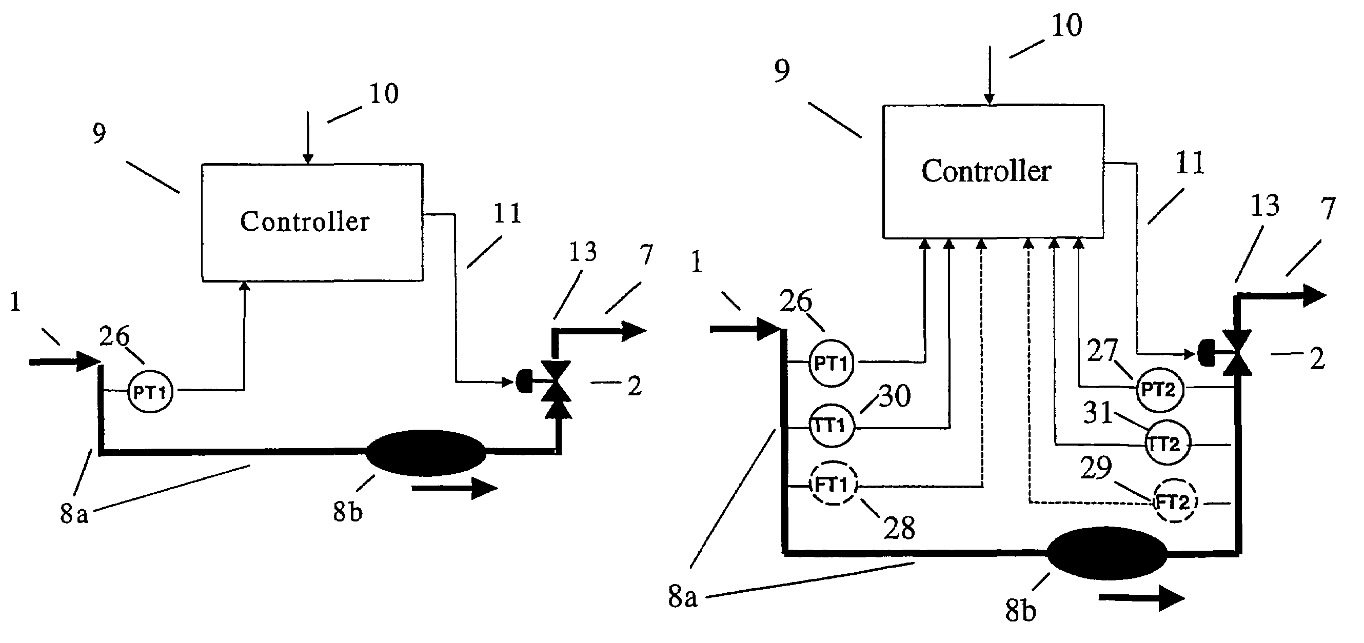
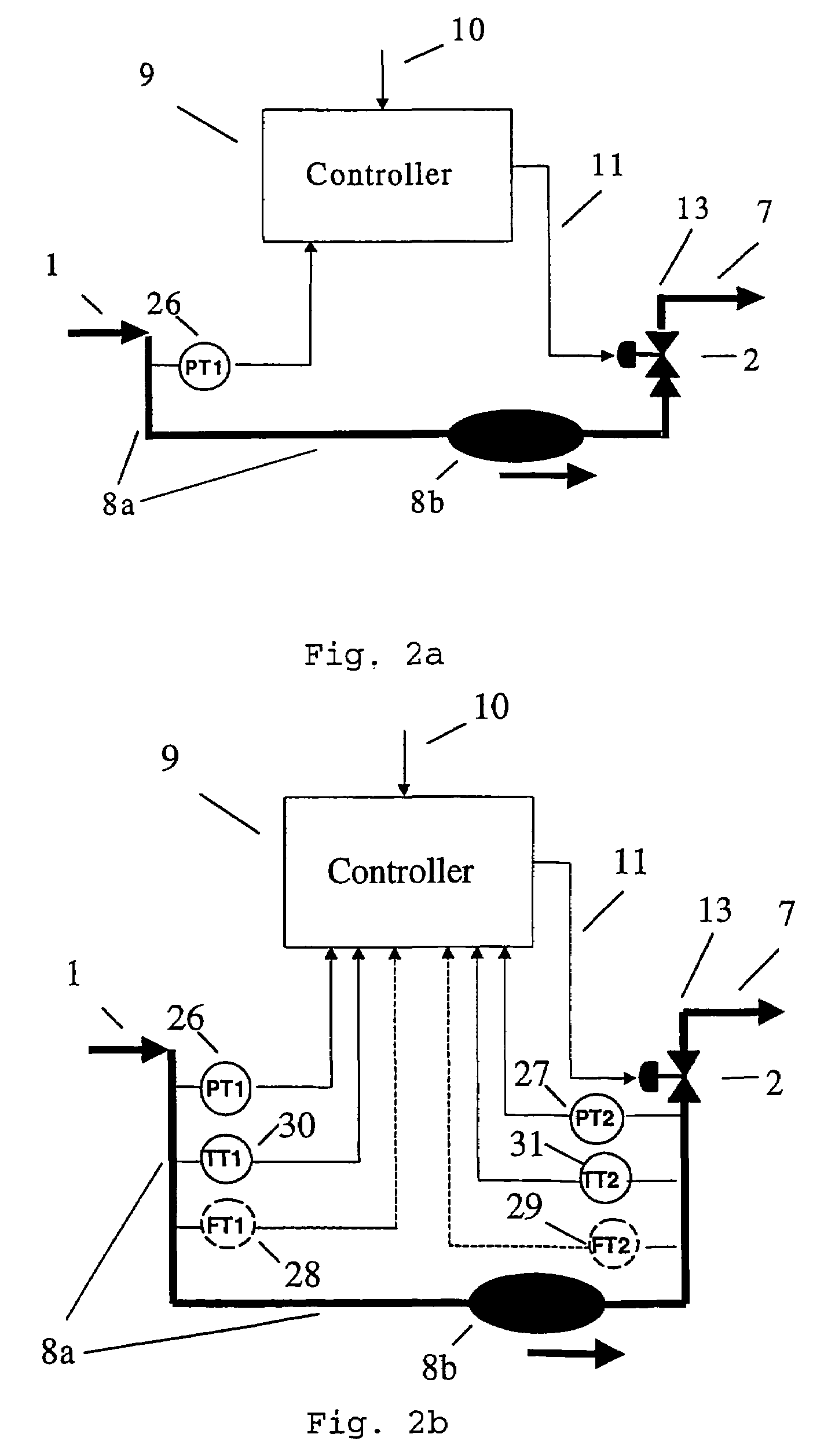
[0073]A method according to the invention for stabilizing a multiphase flow in a flow line 8a, where instability of the multiphase flow is caused by at least one slug 8b, or slugging, comprises the following steps:[0074]measuring continuously one pressure variable 26 upstream the point where the main part of the slug 8b is generated,[0075]supplying at least the pressure variable mentioned above to a dynamic feedback controller,[0076]calculating continuously an output 11 of the dynamic feedback controller 9,[0077]controlling the opening of a control...


PUM

PropertyMeasurementUnit
timeaaaaaaaaaa
volume fractionaaaaaaaaaa
lengthaaaaaaaaaa

Abstract

A method for stabilizing a multiphase flow in a flow line, where instability of the multiphase flow is caused by at least one slug. At least one pressure variable is continuously measured at a flow line inlet upstream of the point where the main part of the slug is generated. The pressure variable is supplied to a dynamic feedback controller, wherein the pressure variable upstream of the slug is an input to the dynamic feedback controller. An output of the dynamic feedback controller is continuously calculated. A control valve at said flow line is controlled by the output from the dynamic feedback controller, wherein the multiphase flow is stabilized throughout the flow line.

Description

CROSS-REFERENCE TO RELATED APPLICATIONS[0001]This application claims priority to Norwegian patent application 20006208 filed Dec. 6, 2000 and is the national phase under 35 U.S.C. § 371 of PCT / IB01 / 02323, filed Dec. 6, 2001.FIELD OF THE INVENTION[0002]The present invention relates to a method for applying a dynamic feedback controller to stabilize multiphase flow in a flow line, such as a pipeline, riser or well production line, where slugs cause instability of the multiphase flow. The invention also relates to a computer program product, which carries out the steps of the method.BACKGROUND OF THE INVENTION[0003]Oil that is produced offshore is transported through pipelines as a complex mixture of oil, gas water and sand. One common flow regime is known as slug flow, in which the mixture flows intermittently along the pipelines and comprises a concentrated mass in the form of a liquid plug. Such a concentrated mass in movement is hereafter called a slug.[0004]In multiphase pipelines...

Claims


Application Information

Patent Timeline
Patent Type & Authority Patents(United States)
IPC IPC(8): G01L7/00G01N11/00E21B43/12F04D31/00G05D7/06
CPCE21B43/121F04D31/00G05D7/0635
Inventor HAVRE, KJETIL
Owner ABB (SCHWEIZ) AG
Why Eureka
Try Eureka