System and method for transferring data on a network using a single route optimizer to define an explicit route and transfer the information related to the explicit route to a plurality of routers and a plurality of optimized routers on the network

Inactive Publication Date: 2007-07-03
SILVER BEECH NETWORKS
View PDF9 Cites 13 Cited by
  • Summary
  • Abstract
  • Description
  • Claims
  • Application Information

AI Technical Summary

Benefits of technology

[0003]In accordance with the invention, it is observed, in this context, that a lower level of network congestion necessitates smaller queues. Less congestion leads to more deterministic operation, and therefore reduced queue lengths. It appears that reduction of network congestion can reduce queue lengths by a factor of at least 1000. Such a reduction in queue length makes practical electronic queuing where it would otherwise be impractical. The most complex and difficult subsystems of a router are queuing, traffic management, and forwarding. It is also observed that traffic engineering is capable, by explicitly scheduling data flows, of eliminating the need for hardware traffic management. And, use of the relatively simple MPLS protocol greatly simplifies the task of electronic forwarding.
[0004]The proper application of traffic engineering, therefore, makes feasible electronics that would otherwise be infeasible, and introduces the possibility of designing a reduced complexity router that is physically smaller, dissipates less power, and has an increased likelihood of timely completion as compared with a conventional IP router. The present invention is directed to the application of traffic engineering to make feasible and practical the design of electronic subsystems as well as for the purpose of improving network throughput. And, it is the application of traffic engineering for the purpose of reducing the complexity of a router such that it is smaller, requires less power, and is more likely to be successfully brought to market.
[0005]A specific and important benefit of a reduced complexity router, as described above, is the ability to use commodity electronic components at higher data rates than would otherwise be possible. This reduces the development cycle by allowing older, readily available, components to be used where ASIC development would otherwise be required.

Problems solved by technology

Such a reduction in queue length makes practical electronic queuing where it would otherwise be impractical.
The most complex and difficult subsystems of a router are queuing, traffic management, and forwarding.
Moreover, this understanding of the nature of aggregated data traffic is contrary to a vast body of current literature on the subject that predicts an absence of smoothing.
The opportunity to develop reduced complexity hardware by use of traffic engineering is thus unavailable to the majority of developers.

Method used


Image

  • System and method for transferring data on a network using a single route optimizer to define an explicit route and transfer the information related to the explicit route to a plurality of routers and a plurality of optimized routers on the network
  • System and method for transferring data on a network using a single route optimizer to define an explicit route and transfer the information related to the explicit route to a plurality of routers and a plurality of optimized routers on the network
  • System and method for transferring data on a network using a single route optimizer to define an explicit route and transfer the information related to the explicit route to a plurality of routers and a plurality of optimized routers on the network

Examples


Embodiment Construction

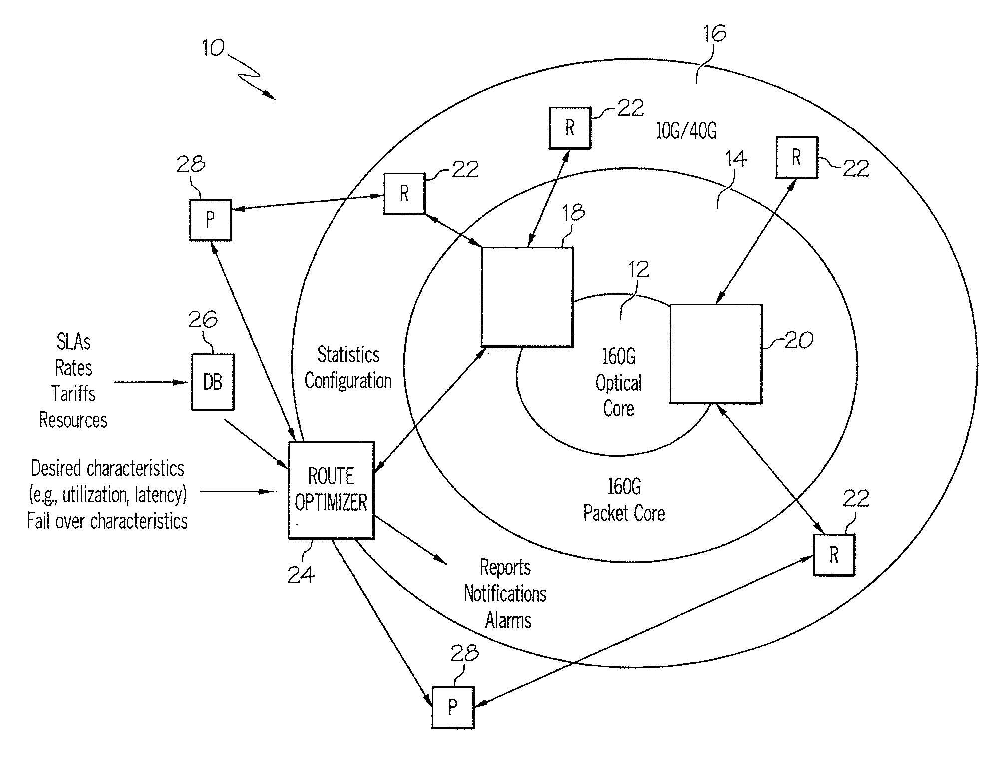
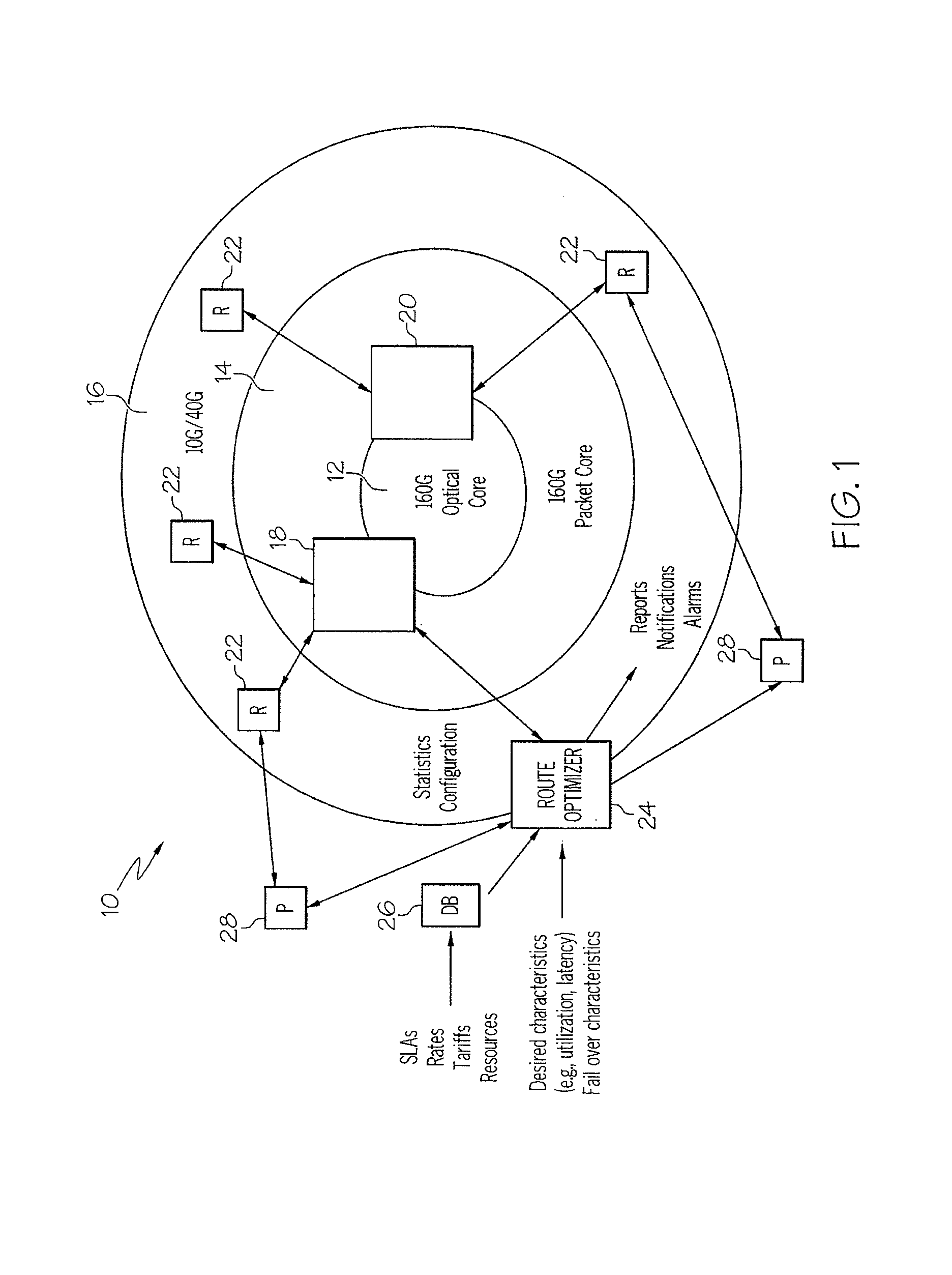
[0018]FIG. 1 is a schematic block diagram of a digital data network 10 implemented in accordance with one embodiment of the invention. The network 10 includes an optical core 12 which can operate at 160 Gb / sec and a packet core 14 which can also operate at 160 Gb / sec. The network 10 also includes a third layer 16 which can operate at 10 Gb / sec, 40 Gb / sec or other speeds. In accordance with the invention, a pair of optimized routers or switches 18 and 20 are connected across the optical core 12. The switches 18, 20 interface with a plurality of routers 22 connected on the network 10. The switches 18, 20 are routers optimized in accordance with the invention such that they have relatively small queue size and reduced hardware complexity.

[0019]At least one of the plurality of routers 22 interfaces with a probe node 28, which interfaces with a route optimizer 24 in accordance with the invention. The probe node is described below in detail. At least one of the switches 18 interfaces with...


PUM


Abstract

An apparatus and method for forwarding data on a digital data network are provided. The network includes optimized routers and a plurality of routers connected on the network. A route optimizer receives information from the optimized routers and plurality of routers with regard to traffic congestion. The information can include queue lengths of one or more queues within the optimized routers. The route optimizer uses the congestion information from the optimized routers and plurality of routers to define optimum paths for transfer of data. The defined paths can be MPLS paths, which are then transmitted to the optimized routers and any other routers in the network.

Description

BACKGROUND OF THE INVENTION[0001]The deployment of optical transmission and switching equipment in data networks has significantly increased data rates over earlier electrical technologies. Optical technology promises to provide an increasing data transmission and switching capability that will quickly exceed that of even the most ambitious electronic designs. Optical transmission and rates of 40 Gb / s, 100 Gb / s, and 160 Gb / s, will soon be implemented in the network core. Switching, however, is a non-deterministic process, subject to congestion, and therefore always requires adjacent queuing. No practical optical queuing mechanism is presently available, and it is clear that such capability, in a practical form, will not be available for many years. As a consequence, fast optical components will require equally fast and large electronic queuing, which will be impractical or impossible to design.[0002]Over the last five years, approximately 85% of hardware-based router projects failed...

Claims


Application Information

Patent Timeline
IPC IPC(8): G06F15/173H04L12/56
CPCH04L45/00H04L45/50
Inventor SCHWARTZ, STEVEN J.HUBER, KATHLEEN
Owner SILVER BEECH NETWORKS
Why Eureka
Try Eureka