Gas generator

a generator and gas technology, applied in the direction of gas generation devices, pressure gas generation, weapons, etc., can solve the problems of increasing the cost of gas generation, and increasing the cost of gas generation, and achieve the effect of simple insulation foil manufacturing

Active Publication Date: 2007-07-10
TRW AIRBAG SYST
View PDF22 Cites 9 Cited by
  • Summary
  • Abstract
  • Description
  • Claims
  • Application Information

AI Technical Summary

Benefits of technology

[0012]A simple manufacture of the insulation foil can be achieved in that the thermally insulating layer is simply sprayed onto the base layer.

Problems solved by technology

In this region, the base layer is then very quickly exposed to the generated heat and is also destroyed more quickly than in the region with the thermally insulating foil layer.

Method used


Image

  • Gas generator
  • Gas generator
  • Gas generator

Examples


Embodiment Construction

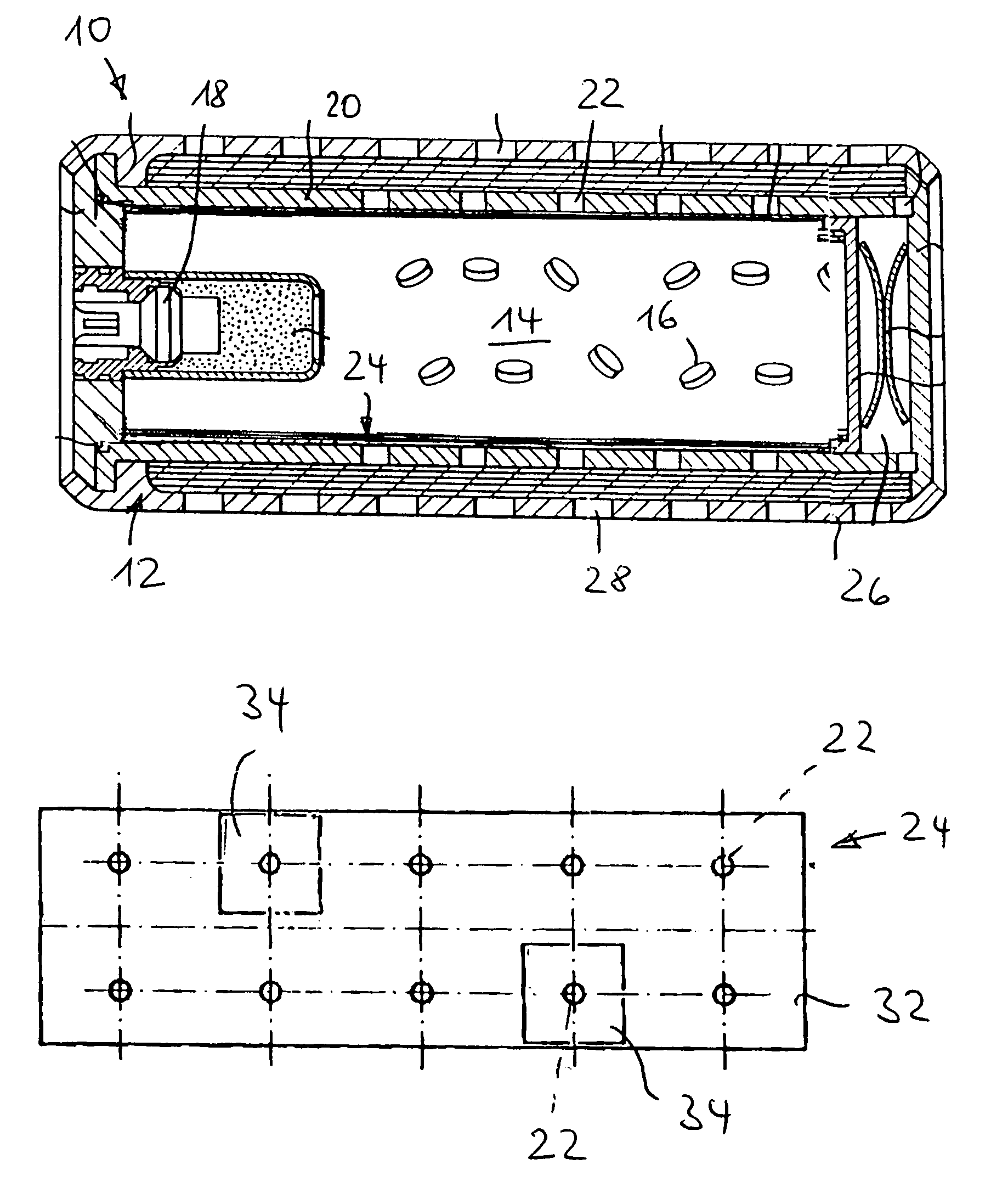
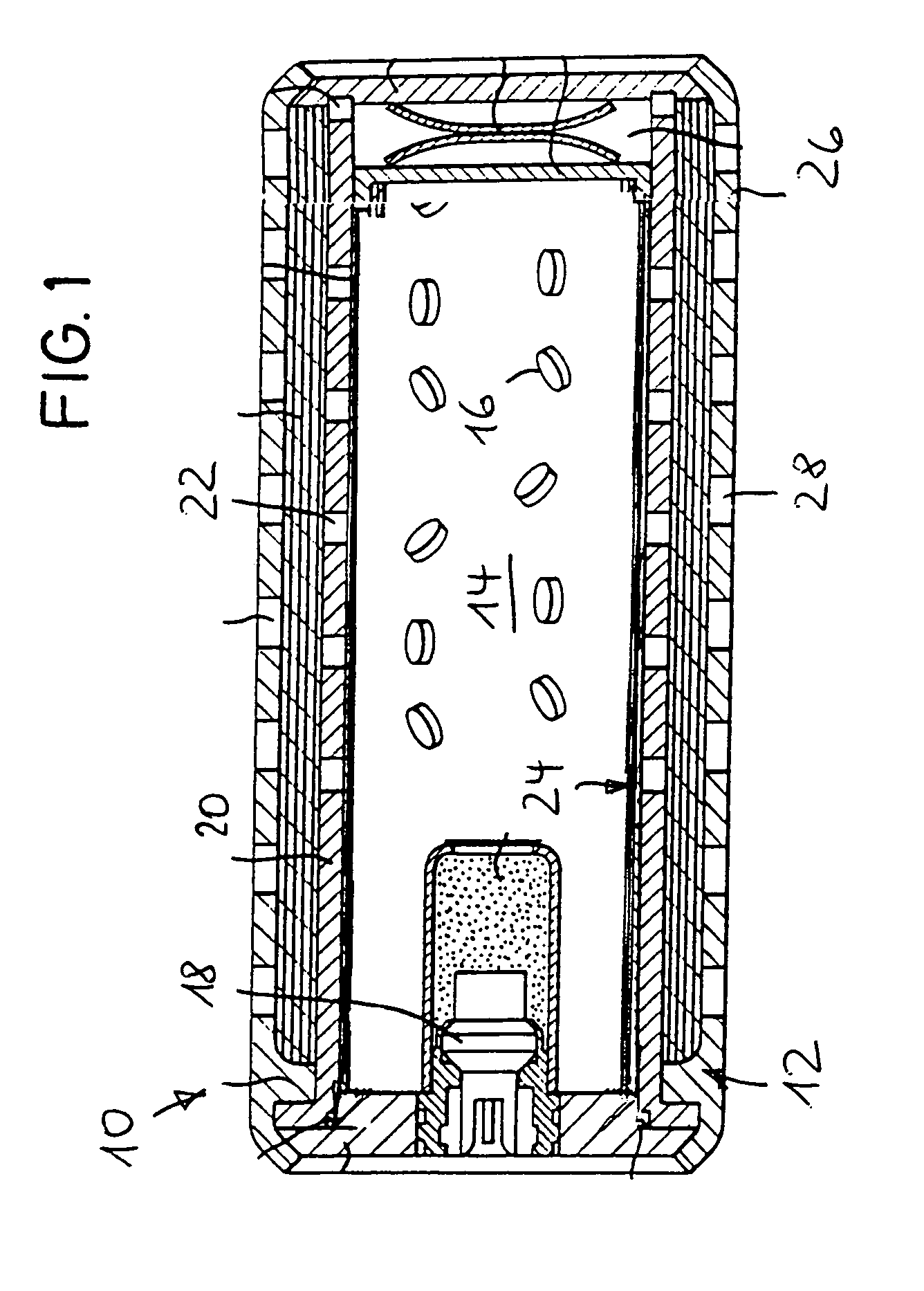
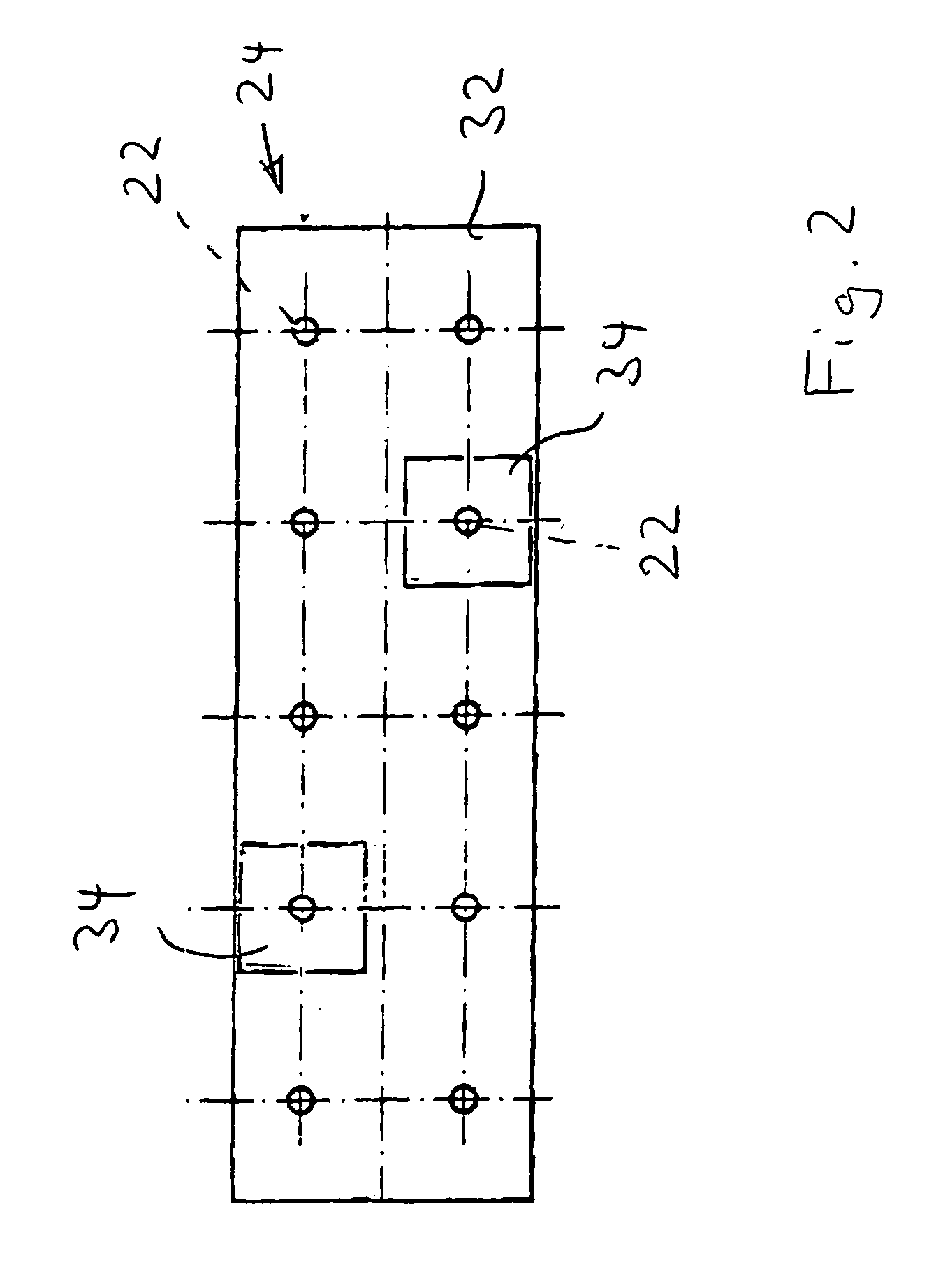
[0021]In FIG. 1 a gas generator 10 is illustrated, which has a housing 12, the housing 12 having walls which define the outer housing and the inner housing. The gas generator has a combustion chamber 14 which is filled with solid propellant 16. The solid propellant 16 can be ignited by an igniter 18. A section of the housing 12 defines the combustion chamber 14; this section is named the combustion chamber wall 20. The combustion chamber wall 20 has on its periphery several uniformly distributed outflow openings 22, which preferably all have the same diameter. An insulation foil 24, which closes all the outflow openings 22, is glued onto the inner side of the combustion chamber wall.

[0022]The housing 12 has in addition an outer wall 26 which is likewise provided with outflow openings 28. On the inner side of the outer wall 26, an insulation foil 24 can likewise be provided, this insulation foil 24 being provided additionally or alternatively to the insulation foil 24 lying on the in...


PUM


Abstract

A gas generator includes a housing, which has outflow openings for outflowing gas, and at least one destructible insulation foil which in a non-activated state of the gas generator closes at least one of the outflow opening so as to be moisture-tight. The insulation foil has a varying thickness. The varying thickness is provided by at least one thermally insulating foil layer with a varying thickness, which lies over a base layer.

Description

TECHNICAL FIELD[0001]The invention relates to a gas generator with a housing which has outflow openings for outflowing gas.BACKGROUND OF THE INVENTION[0002]A gas generator of this type normally has, in addition, at least one destructible insulation foil which in the non-activated state of the gas generator closes at least one of the outflow openings so as to be moisture-tight, the insulation foil having a varying thickness.[0003]A generic gas generator is known from DE 38 31 641 A1. The insulation foil closes off the outflow openings over a period of years, so as not to allow any moisture to reach the solid propellant. By insulation foil of varying thickness, the resistance of the insulation foil on opening can be adjusted and thereby the pressure inside the gas generator in the initial phase of combustion can be varied. The burning behavior is altered hereby. At high ambient temperatures of over 75° C. up to 90° C., propellant burns substantially faster than at low ambient temperat...

Claims


Application Information

Patent Timeline
Patent Type & Authority Patents(United States)
IPC IPC(8): B60R21/26B60R21/264
CPCB60R21/2644
Inventor BIERWIRTH, SEBASTIANHOFMANN, ACHIMSCHWUCHOW, KARSTEN
Owner TRW AIRBAG SYST
Why Eureka
Try Eureka