Supercharge Your Innovation With Domain-Expert AI Agents!

Optical recording system with optimal recording laser beam power control, and method and device for generating a mark formation effectiveness signal in an optical recording system

a recording system and laser beam technology, applied in the direction of recording signal processing, digital signal error detection/correction, instruments, etc., can solve the problems of occurrence of the peak value of reflected write, information cannot be completely recorded, and damage to recorded tracks

Inactive Publication Date: 2007-07-10
MEDIATEK INC
View PDF3 Cites 2 Cited by
  • Summary
  • Abstract
  • Description
  • Claims
  • Application Information

AI Technical Summary

Benefits of technology

[0010]Therefore, the main object of the present invention is to provide an optical recording system capable of generating optimal recording laser beam power automatically to overcome the aforesaid drawbacks associated with the prior art.
[0011]Another object of the present invention is to provide a method and device for generating mark formation effectiveness signals in an optical recording system to optimally control the power of a recording laser beam.
[0024]a light source controller coupled to the laser light source and the signal generating device, the light source controller controlling recording laser beam power of the laser light source according to the mark formation effectiveness signal from the signal generating device for optimum information recording.

Problems solved by technology

Therefore, when the recording signal power is too low, information cannot be completely recorded.
Furthermore, when the recording signal power is too high, damage to recorded tracks can occur.
1. Ideally, the first sample-hold circuit 12 samples a maximum power level of the reflected write pulse (WRF). In practice, the timing of occurrence of the peak value of the reflected write pulse (WRF) is not fixed, and is actually subject to change according to various factors, such as changes in the thickness of recording dye layer and substrate characteristics of optical recording media, skewing of the optical recording medium, etc. Since the time of sampling by the first sample-hold circuit 12 is fixed, and since the actual occurrence of the peak value of the reflected write pulse (WRF) is instantaneous, the first sample-hold circuit 12 is usually unable to detect the peak value of the reflected write pulse (WRF).
2. The first and second sample-hold circuits 12, 13 are coupled to the first and second A / D converters 15, 16, respectively. When additional sample-hold circuits are installed to increase the number of sampled values of the reflected write pulse (WRF), a corresponding increase in the number of the A / D converters will be required as well. This not only results in increased manufacturing costs, but also complicates the entire circuit configuration.

Method used


Image

  • Optical recording system with optimal recording laser beam power control, and method and device for generating a mark formation effectiveness signal in an optical recording system
  • Optical recording system with optimal recording laser beam power control, and method and device for generating a mark formation effectiveness signal in an optical recording system
  • Optical recording system with optimal recording laser beam power control, and method and device for generating a mark formation effectiveness signal in an optical recording system

Examples


Embodiment Construction

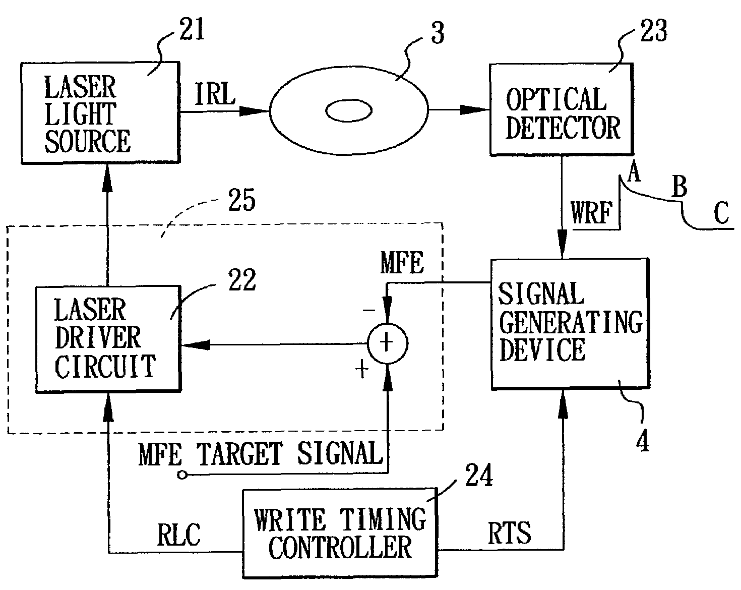
[0039]FIG. 4 illustrates the preferred embodiment of an optical recording system according to the present invention. The optical recording system is adapted to be loaded with an optical recording medium 3, and is shown to include a laser light source 21, a light source controller 25 coupled to the laser light source 21 for driving operation of the same, an optical detector 22, a signal generating device 4 coupled to the optical detector 22, and a write timing controller 24. The laser light source 21 is a laser diode, and is operable so as to provide an incident recording light signal (IRL) (see FIG. 6B) for recording information on the optical recording medium 3 in a known manner. The light source controller 25 includes a laser driver circuit 22. The write timing controller 24 provides a recording laser control signal (RLC) (see FIG. 6A) and write timing pulses (RTS) (see FIG. 6D). The recording laser control signal (RLC) is used for controlling the laser driver circuit 22 to drive ...


PUM

PropertyMeasurementUnit
poweraaaaaaaaaa
thicknessaaaaaaaaaa
temperatureaaaaaaaaaa

Abstract

An optical recording system includes a laser light source that provides an incident recording light signal for recording information on an optical recording medium, an optical detector for detecting a reflected write pulse from the optical recording medium, and a light source controller for controlling recording laser beam power of the laser light source according to a mark formation effectiveness signal generated by a signal generating device. The signal generating device includes an analog peak value detector for detecting a peak value of the reflected write pulse from the optical detector, at least one sample-hold circuit for sampling the reflected write pulse to obtain at least one amplitude value, and a processor for generating the mark formation effectiveness signal according to the peak value and the amplitude value.

Description

CROSS REFERENCE TO RELATED APPLICATIONS[0001]This application claims priority to Taiwanese application No. 091112414, filed Jun. 7, 2002.BACKGROUND OF THE INVENTION[0002]1. Field of the Invention[0003]The invention relates to an optical recording system with optimal recording laser beam power control, more particularly to an optical recording system using a method and device for generating mark formation effectiveness signals to optimally control the power of a recording laser beam.[0004]2. Description of the Related Art[0005]To record information on an optical recording medium, a light source of an optical recording system, such as a laser diode that is driven by a laser driver circuit according to a write control signal, generates an incident recording light signal on the optical recording medium. To assure that data is correctly recorded, it is important that the laser output must be maintained at an appropriate power level. The optimal power control (OPC) technique is widely emp...

Claims


Application Information

Patent Timeline
Patent Type & Authority Patents(United States)
IPC IPC(8): G11B7/125G11B7/0045
CPCG11B7/00458G11B7/1263
Inventor CHEN, CHIH-CHENGLIU, DING-JENTSAI, SHUN-FANGCHAU, MING-YANG
Owner MEDIATEK INC
Features
  • R&D
  • Intellectual Property
  • Life Sciences
  • Materials
  • Tech Scout
  • Unparalleled Data Quality
  • Higher Quality Content
  • 60% Fewer Hallucinations
Learn More