Low-water cut-off system

a technology of low-water cut-off and cut-off valve, which is applied in the direction of liquid/fluent solid measurement, instruments, machines/engines, etc., can solve the problem that the probe no longer detects the electric current generated by the device through the conductive fluid, and achieves the effect of preventing rapid shutting of the device, increasing detection sensitivity, and easily and easily adjusting the time delay

Inactive Publication Date: 2007-07-17
NAT CITY BANK CO
View PDF26 Cites 21 Cited by
  • Summary
  • Abstract
  • Description
  • Claims
  • Application Information

AI Technical Summary

Benefits of technology

[0024]provides utility and precision as well as highly reliable operation both for low-pressure and hot water boilers to cut off a burner for the boiler if there is sensed a low water level (or other low fluid level) condition;
[0048]According to a further aspect of improvement of the system as contrasted to the known art, system not only provides for controllable scaling, or attenuating, of the input signal provided by a signal passing through water to be monitored at a current level which is dependent upon the conductance of the water, but also operates with a signal comparison threshold sp as to assure stable operation by the monitoring circuitry of the system. Further, the system includes circuitry defining signal chains which operate in modes differently defined in such a way that both chains must correctly sense for the presence of water monitored by the low water cut-off system, so as to provide redundancy establishing a further fail-safe characteristic.

Problems solved by technology

However, if fluid level falls below the probe, the probe no longer detects electric current generated by the device through the conductive fluid.

Method used


Image

  • Low-water cut-off system
  • Low-water cut-off system
  • Low-water cut-off system

Examples


second embodiment

Operation of Second Embodiment

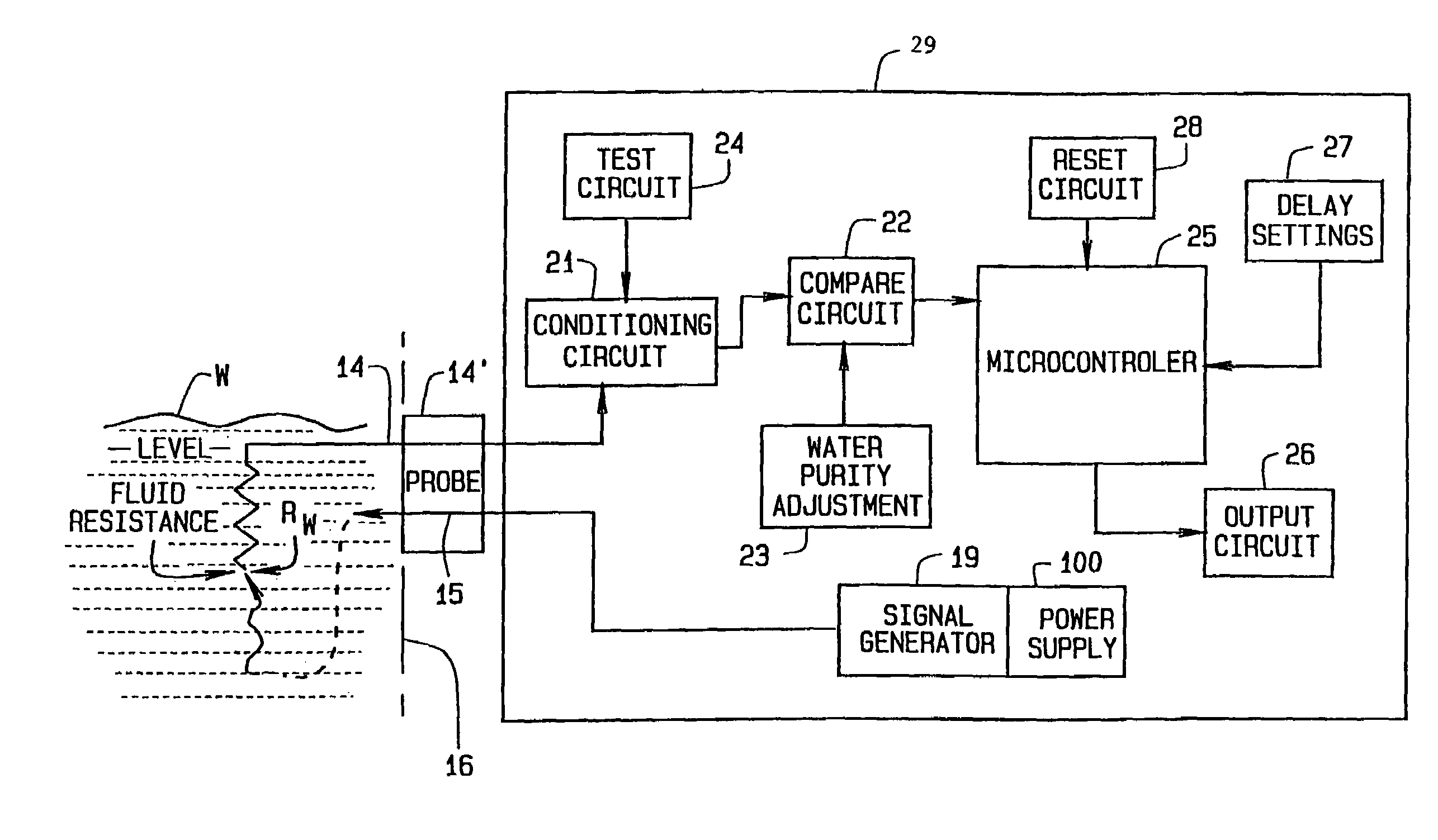
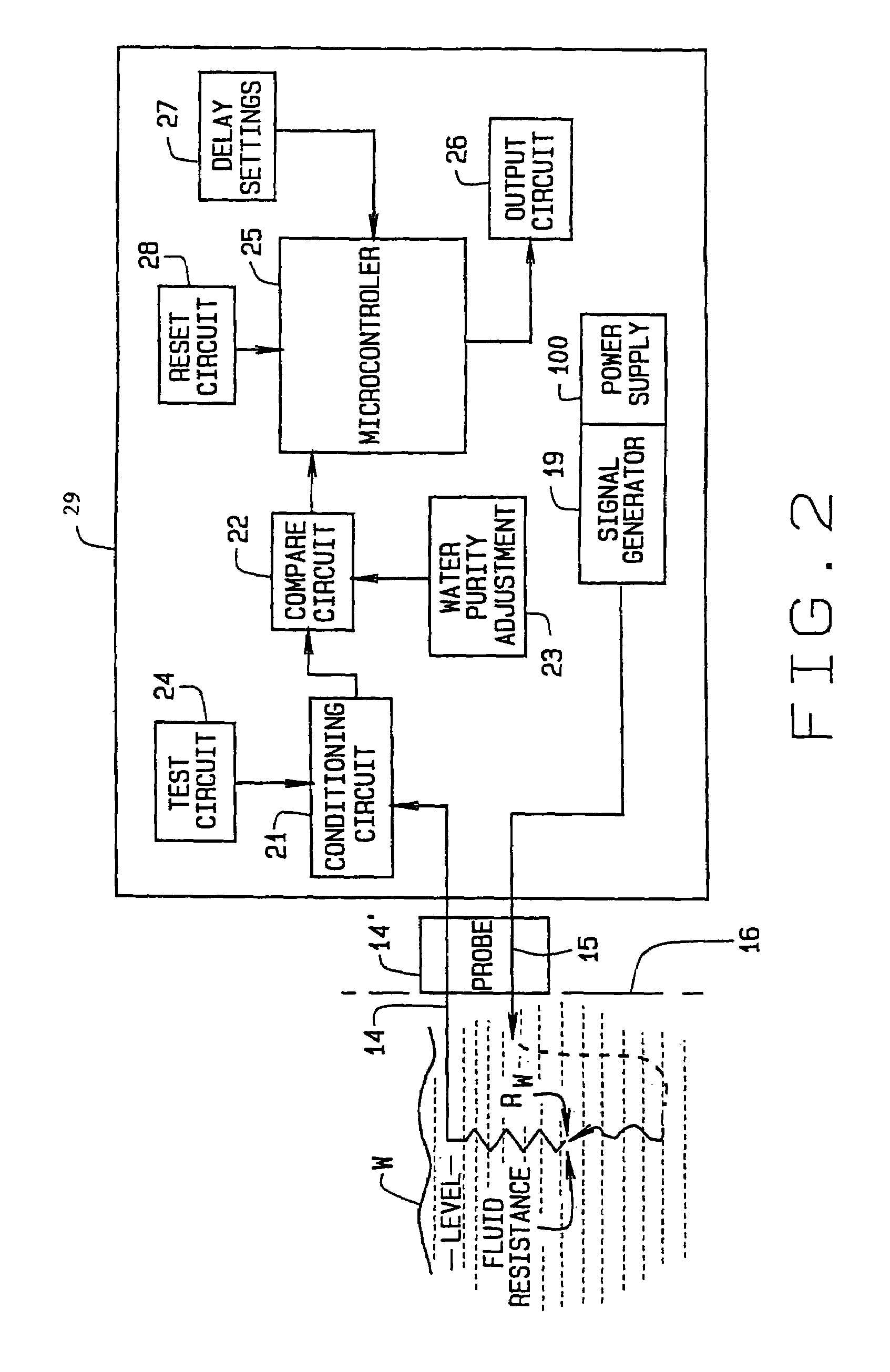
[0083]Networks 122A and 122B are mutually cooperative, providing a functional effect of logic AND gating to ensure that if there is sufficient vessel level of water, as accommodated according to its purity by adjustment of pentiometer R1, both transistors Q1 and Q2 are normally driven to a conductive state. The series collector-emitter circuits provided by Q1 and Q2 is supplied with voltage from the power supply 110 through a diode B16. When transistors Q1 and Q2 both are in their conductive state, relay K1 becomes energized and enabled which is representative of a normal water level in the boiler. If water is not present, i.e. a low water condition exists, Q1 and Q2 are cutoff and become non-conducting, thus de-energizing K1 which indicates a low water condition.

[0084]Referring again to the output circuit 126, should either of transistors Q1 and Q2 revert to an “off” stage, as in the event of insufficient water in vessel 16, or in the unlikely event of...


PUM


Abstract

A low-water cut-off system [A] determines if fluid [W] within a boiler or other enclosure drops below a predetermined level within the enclosure. A signal generator introduces a signal into the enclosure so that the signal is present for sensing at the predetermined level, where a probe is provided for sensing the signal if present as occurs if the water is at the predetermined level. A control, which includes a microcontroller, is responsive to the probe for providing a control function in response to whether the signal is so sensed by the probe, and so to determine if water has dropped below the predetermined level. The function may be causing alarm signalling or boiler heating cut-off. Self-test and time delay features are also included. Provision is made so that the control compensates for variation in electrical conductivity of the water through which the probe signal is sent, including circuitry to adjust for a wide range of possible purity levels. Provision is included such that the low water cut-off system is fault tolerant no matter at what water purity it is adjusted to operate.

Description

CROSS-REFERENCE TO RELATED APPLICATION[0001]This application is a continuation-in-part of application Ser. No. 10 / 154,730, filed May 24, 2002, now U.S. Pat. No. 6,904,800 which claims priority from U.S. Provisional Patent Application Ser. No. 60 / 293,444, filed May 24, 2001.BACKGROUND OF THE INVENTION[0002]1. Field of the Invention[0003]The present invention relates to fluid level detection systems and, more particularly, to an advantageous low-water cut-off system that operates in any of a wide range of conditions and provides precise level detection with an extraordinarily wide variety of electrically conductive fluids.[0004]Although the term low water cut-off system is herein used, it will be understood as being applicable to systems using fluids other than water which exhibit electrical conductivity that can be sensed for the present purposes. The term low water cut-off system is used in its general sense, regardless of the fluid to be sensed.[0005]2. Known Art[0006]Low water cut...

Claims


Application Information

Patent Timeline
Patent Type & Authority Patents(United States)
IPC IPC(8): G01F23/26G01F23/24
CPCG01F23/243
Inventor MERWIN, JEFFREY
Owner NAT CITY BANK CO
Why Eureka
Try Eureka