Relative pressure sensor having an atmosphere-side damper

a technology of relativity and damper, applied in the field of relativity pressure sensors, can solve the problems of insufficient solution, inability to effectively damped needle pulses, and inability to achieve effective damping, etc., and achieve the effect of sufficiently rapid transmission and low fluctuation

Inactive Publication Date: 2007-07-17
EHNDRESS KHAUZER GMBKH KO KG
View PDF11 Cites 2 Cited by
  • Summary
  • Abstract
  • Description
  • Claims
  • Application Information

AI Technical Summary

Benefits of technology

[0012]Slow volume flows through the damper are, in contrast, quite possible, so that, on the one hand, an equalizing of volume changes of the transmission liquid due to temperature changes can occur, and, on the other hand, the relatively slow fluctuations of the ambient, or atmospheric, pressure can be transmitted sufficiently quickly to the measuring membrane.

Problems solved by technology

This means, however, negatively, that the pressure-sensitive elements are very sensitive to needle-like pressure spikes, since scarcely any elasticity is present for absorbing such, so that a destruction of the measuring cell can result.
By simple lessening of the diameter of the pressure supply line between the process-side chamber and the pressure-sensitive element, the needle pulses cannot be effectively damped, or attenuated.
This solution is not satisfactory for various reasons.
On the one hand, the reduction of the hydraulic path between process and measuring cell to even a single bore of 0.5 mm diameter and bore length such as is to be expected from the shown plate thickness, offers, by far, no sufficient damping for suppressing needle-shaped, overloading, pressure spikes.
On the other hand, if a damping element of a sufficiently great flow resistance for an effective damping is provided, then the reaction velocity of the sensor is significantly slowed, so that then pressure fluctuations within the measuring range of the sensor are registered only with delay.

Method used


Image

  • Relative pressure sensor having an atmosphere-side damper
  • Relative pressure sensor having an atmosphere-side damper
  • Relative pressure sensor having an atmosphere-side damper

Examples


Embodiment Construction

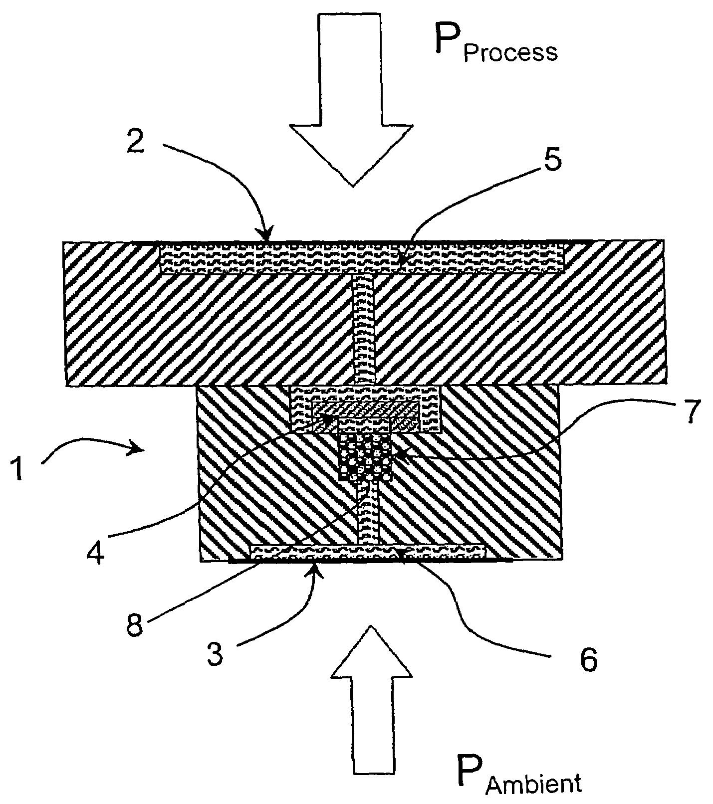
[0021]The relative pressure sensor shown in FIG. 1 includes a measuring unit 1 having a first chamber 5, which is sealed on the process-side by a first separating membrane 2, and a second chamber 6, which is sealed on the atmosphere-side by a second separating membrane 3. Inside the measuring unit 1 is a pressure-sensitive element 4, which includes a measuring membrane, or diaphragm. The pressure-sensitive element 4 separates the first chamber 5 from the second chamber 6. In the preferred form of embodiment, the pressure-sensitive element is a piezoresistive silicon chip. In principle, the invention is, however, independent of the principle by which the pressure-sensitive element works.

[0022]The first chamber and the second chamber are completely filled with a transmission medium, preferably a silicone oil.

[0023]Arranged in the second chamber is a damper 7. To this end, the second chamber includes a bore 8, in which the damper is fixed by a force fit. Additionally, the damper is axi...


PUM

PropertyMeasurementUnit
pore diameteraaaaaaaaaa

Abstract

A relative pressure sensor comprises two chambers and two separating membranes respectively provided for a process pressure and an ambient pressure. The chambers are separated by a pressure-sensitive element and are filled with a transmission medium. In order to attenuate process-side overload pulses, which act upon the first separating membrane, a hydraulic damper is provided that is placed on the side of the atmosphere between the second separating membrane and the pressure-sensitive element. The pressure-sensitive element is a piezoresistive silicon chip, the transmission medium consists of silicone oil, and the damper is comprised of a filter element made of sintered bronze having 29% porosity and an 11 micrometer pore diameter. The filter element has a length of 8 mm and a diameter of 2 mm.

Description

FIELD OF THE INVENTION[0001]The present invention relates to a relative pressure sensor with hydraulic pressure transmission.BACKGROUND OF THE INVENTION[0002]Such pressure sensors include, as a rule, a measuring unit with two chambers, each of which is sealed by a separating membrane, or diaphragm, and filled with a transmission medium. The separating membranes are loaded, respectively, with a pressure being measured and with a reference pressure. These pressures are transmitted via the separating membranes into the respective chambers. The chambers are separated from one another by a sensor element in the form of a pressure sensitive element, especially a measuring membrane, which is loaded on its first surface with the hydraulic pressure in the first half-cell and on its second surface with the hydraulic pressure in the second half-cell.[0003]The present invention relates to a relative pressure sensor with hydraulic pressure transmission. Such pressure sensors include, as a rule, ...

Claims


Application Information

Patent Timeline
Patent Type & Authority Patents(United States)
IPC IPC(8): G01L7/08G01L9/00G01L19/06
CPCG01L19/0609G01L19/0645
Inventor DANNHAUER, WOLFGANGBURCZYK, DIETFRIED
Owner EHNDRESS KHAUZER GMBKH KO KG
Why Eureka
Try Eureka