Elevator safety brake, elevator and method for testing elevator safety brakes

a technology for elevators and brakes, applied in the direction of elevators, apparatus for force/torque/work measurement, hoisting equipment, etc., can solve the problems of inability to detect the mechanical failure of one of the brakes in the pair, the elevator may operate a long time hiccuping on one brake, etc., to achieve the effect of small size, low cost, and fast operation

Active Publication Date: 2020-02-27
KONE CORP
View PDF0 Cites 0 Cited by
  • Summary
  • Abstract
  • Description
  • Claims
  • Application Information

AI Technical Summary

Benefits of technology

[0023]One significant advantage of the invention is that the operation condition testing of the safety brakes is fast, cost effecting and easy to perform. Another advantage is that the safety brake units can be small in their size and cost effective. The dimensioning of the brake units becomes smaller when the number of brake plates or armatures increases. This means that the brake unit is cheaper to manufacture and it fits into a smaller space. In addition, the braking torque is not too high, which might otherwise cause an uncomfortably high deceleration for elevator passengers in some emergency stop situations. Yet another advantage is higher ride comfort due to decreased deceleration fluctuation as well as a quieter operation of the brakes. Further, thanks to at least two brake units with two or more movable brake elements like brake plates with brake pads or armatures with brake bands or linings a failure of a brake part decreases the usable braking torque only a little, and the brake arrangement remains operable. Yet a further advantage of the inventive test method according to the invention i...

Problems solved by technology

In addition, the elevator car must stay in its position in a floor also in overload situations.
In addition, the brake arrangement must be fault tolerant so that one mechanical fault is not able to make the brake arrangement totally inoperative.
A problem with this kind of a use is that a mechanical failure of one of the brakes in the pair is not necessarily discovered.
In that case the elevator may operate a long time hinging on one brake only.
This...

Method used


Image

  • Elevator safety brake, elevator and method for testing elevator safety brakes
  • Elevator safety brake, elevator and method for testing elevator safety brakes
  • Elevator safety brake, elevator and method for testing elevator safety brakes

Examples


Embodiment Construction

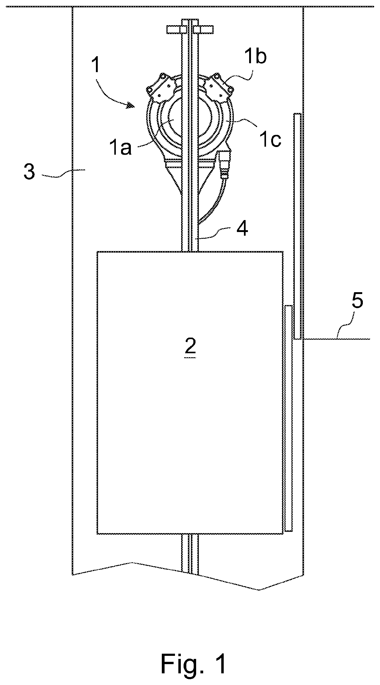
[0034]FIG. 1 presents in a simplified and diagrammatic side view a part of the building where a sidewall of an elevator shaft 3 is removed, and an elevator car 2 is approaching the uppermost floor level 5. An elevator driving machinery 1 with a traction sheave 1a, two operating safety brake units 1b and a brake disc 1c is preferably fastened to a guide rail 4 at the upper end of the elevator shaft 5. In this embodiment of the invention the safety brake units 1b are disc brakes.

[0035]The elevator is a so-called Machine-Room-Less (MRL) elevator where the elevator driving machinery 1 with its operating brake units 1b and traction sheave 1a is in the elevator shaft 3 or in an appropriate space adjacent to the elevator shaft 3, and preferably in the upper area of the elevator shaft, advantageously just below the ceiling of the elevator shaft 3. The elevator car 2 is arranged to run up and down in the elevator shaft 3 along guide rails 3 guided by guide shoes. In addition, the elevator co...


PUM


Abstract

An elevator safety brake unit, an elevator including at least two of the safety brake units, and a method for testing the safety brake units are disclosed. Each safety brake unit includes a frame part, a movable composition movably supported on the frame part, a compression spring assembly associated with the movable composition, and adapted to activate a braking by pushing the movable composition forward, and a coil assembly of an electromagnet disposed in the frame part and adapted to deactivate the braking by pulling the movable composition backwards. Each movable composition includes at least two movable elements, one compression spring for each movable element, and at least one coil assembly adapted to deactivate the braking by pulling the at least two movable elements backwards.

Description

FIELD OF THE INVENTION[0001]The present invention relates to an elevator safety brake as defined in the preamble of claim 1, an elevator as defined in the preamble of claim 8 and a method for testing elevator safety brakes as defined in the preamble of claim 11.BACKGROUND OF THE INVENTION[0002]Elevators are commonly used to carry people up and down in buildings. The passenger safety in elevators is one of the most important aspects. It must be controlled that the elevator car cannot fall freely downwards or move uncontrolled upwards. Also, all accelerations and decelerations must be kept in certain safe limits. And further, an elevator car must stop substantially smoothly in a correct place at the floor where it is landing. Additionally, the elevator car must be able to leave the floor substantially smoothly. In addition, the elevator car must stay in its position in a floor also in overload situations.[0003]For the reasons mentioned above the authorities in different countries have...

Claims


Application Information

Patent Timeline
IPC IPC(8): B66B5/20B66B5/00G01L5/28B66B1/32
CPCB66B5/20B66B5/0093G01L5/28B66B1/32B66D5/30B66D5/14B66D5/08F16D65/14F16D65/0973F16D65/06F16D65/04B66B11/043F16D2121/20B66B5/0037
Inventor LAPPALAINEN, JONIWENLIN, HENRISAARELAINEN, ANTTIALKULA, PETRIHURRI, LASSEBURAKOV, ANDREJRANTA, LEENA
Owner KONE CORP
Why Eureka
Try Eureka