Telescoping buoyancy capsule

a technology of buoyancy capsules and telescopic devices, which is applied in the field of buoyancy capsules, can solve the problems of no weapons/vehicles presently used by the navy that are designed for continuous seawater emergency

Inactive Publication Date: 2007-07-17
UNITED STATES OF AMERICA
View PDF9 Cites 9 Cited by
  • Summary
  • Abstract
  • Description
  • Claims
  • Application Information

AI Technical Summary

Benefits of technology

[0014]It is a further object of the present invention to provide a capsule that is stored in a collapsed or unextended state in order to save space.
[0015]It is a still further object of the present invention to provide a capsule that is stored in a collapsed or unextended state in order to save space therefore allowing storage space within the payload module to be conserved.
[0016]It is a still further object of the present invention to provide a capsule in which launch depth capability is improved by minimizing the size of the protective capsule while maintaining a given wall thickness of comparatively larger capsules.
[0017]It is a still further object of the present invention to provide a capsule that minimizes gas generation for launching weapons.
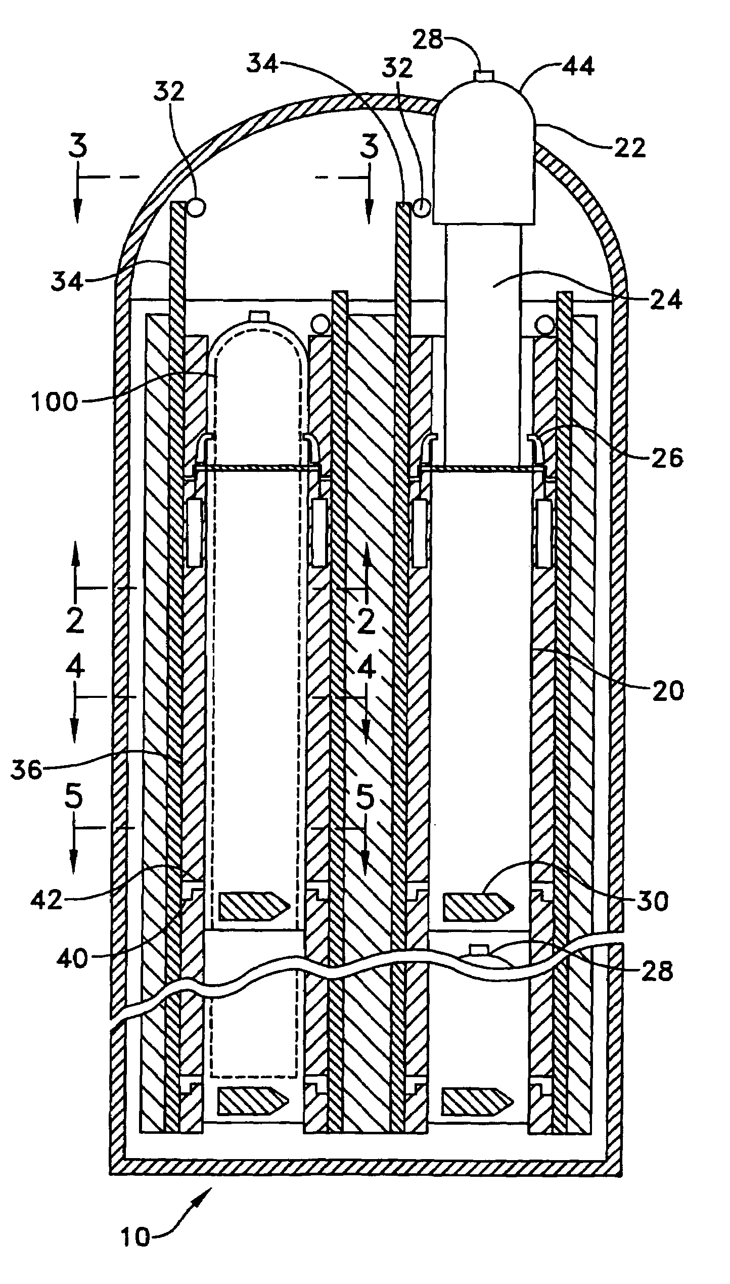
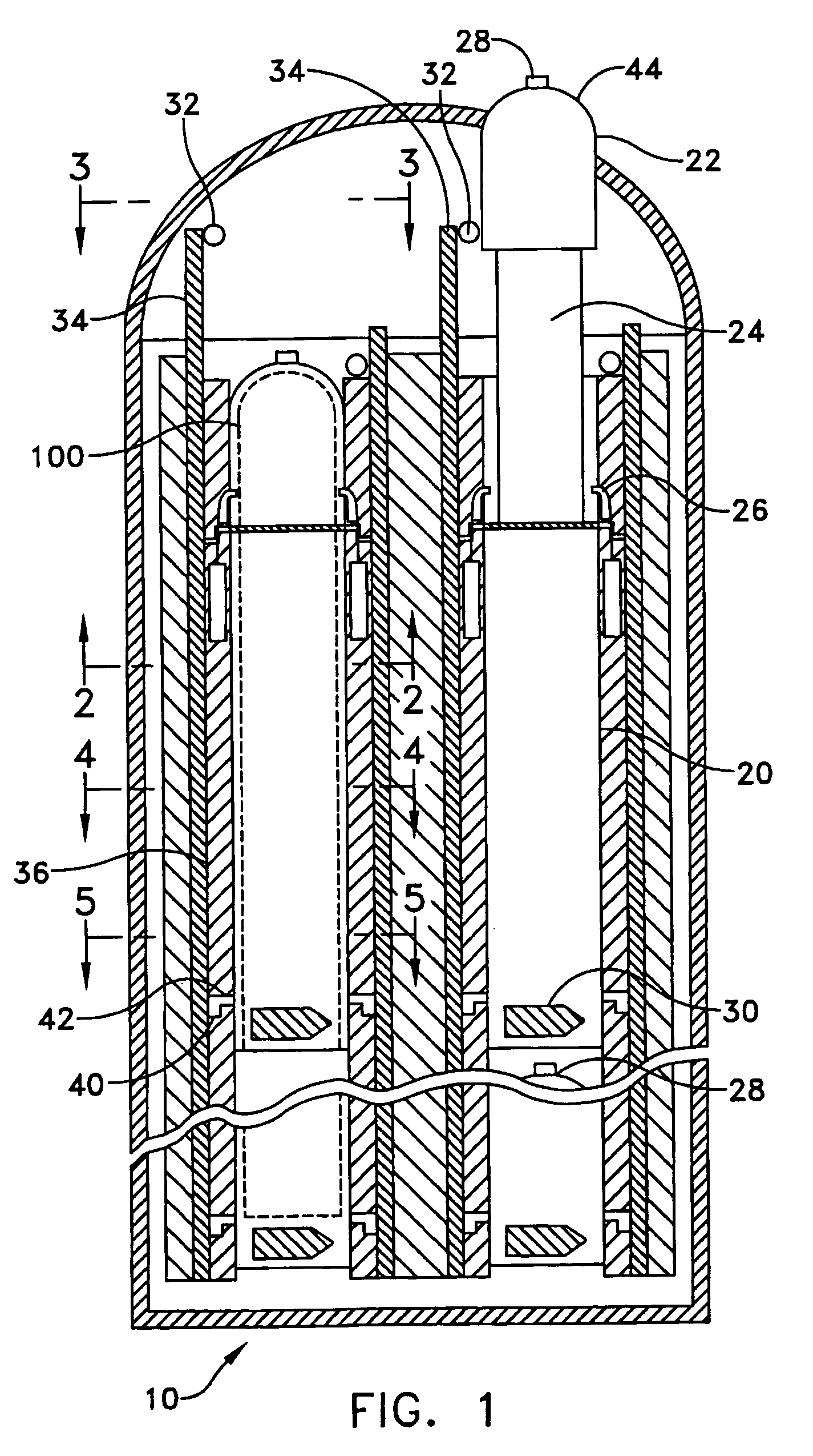
[0019]A telescoping nose section allows the volume of the capsule section to be minimized for maximum packing density and allows the volume of the capsule to be increased without increasing the weight of the capsule. The telescoping nose section normally remains unextended around the weapon contained within the capsule. However when extended, the greater volume of the extended telescoping nose section provides the necessary buoyancy used to lift the capsule out of a stored state and to ascent the capsule towards the surface.

Problems solved by technology

Presently, no weapons / vehicles presently used by the Navy are designed for continuous seawater emersion.

Method used


Image

  • Telescoping buoyancy capsule
  • Telescoping buoyancy capsule
  • Telescoping buoyancy capsule

Examples


Embodiment Construction

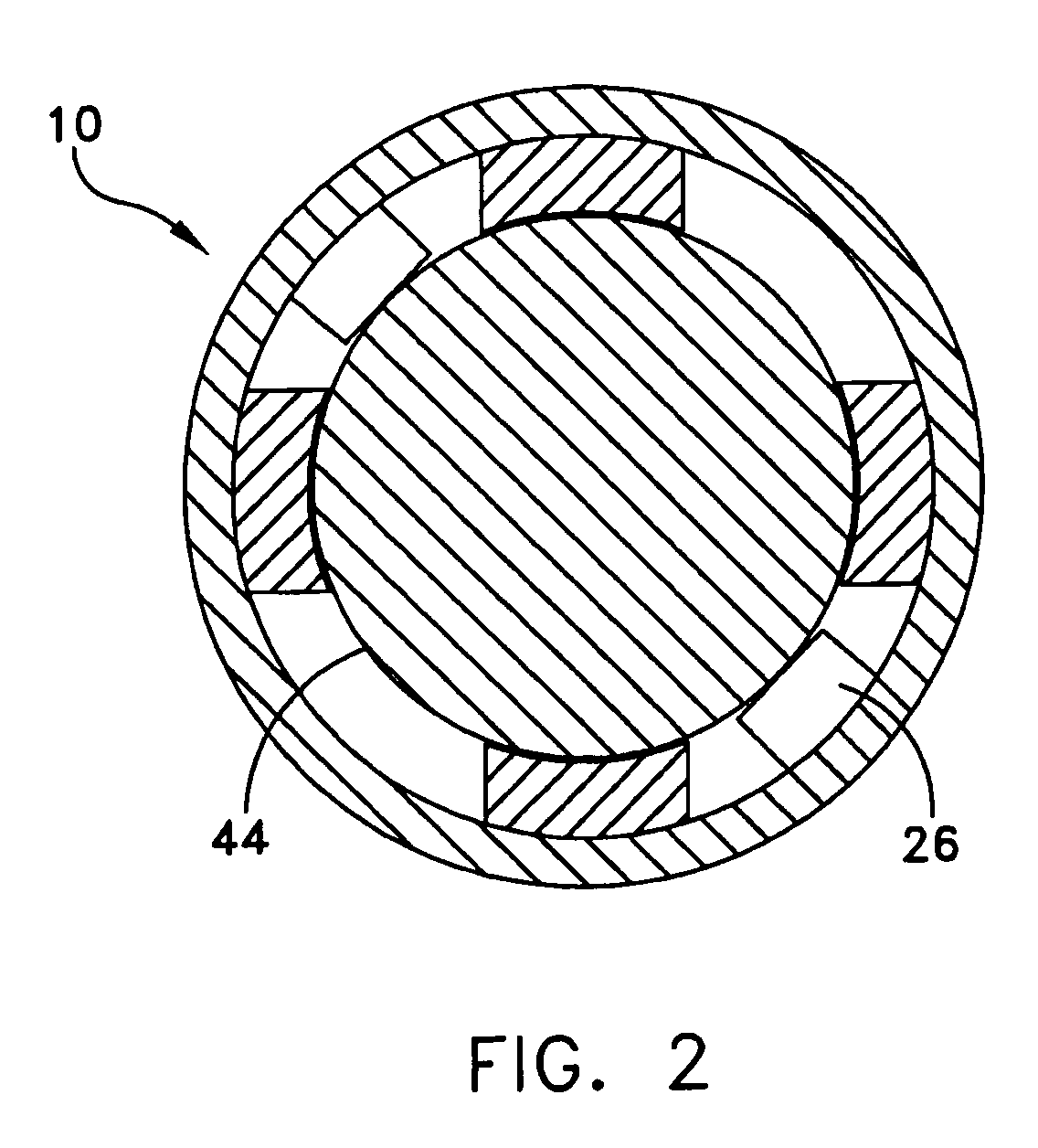
[0030]Referring now to the drawings in detail wherein like numerals indicate like elements throughout the several views, the telescoping buoyancy capsule system 10 of the present invention is shown in FIG. 1. In use with a submarine or other undersea platform (not shown), a telescoping buoyancy capsule 20 of the telescoping buoyancy capsule system 10 could be built as part of a larger modular payload bay.

[0031]The telescoping buoyancy capsule 20 is preferably a rigid cylindrical body sized to contain a vehicle or weapon 100 and is designed to withstand operating depth pressures. The weapon 100 may be many sizes, know to those skilled in the art and capable of utilizing the buoyancy that the telescoping buoyancy capsule system 10 provides. The rigid cylindrical body of the capsule 20 also protects the weapon 100 during an ascent to the water surface. Once the surface is reached, a nose cone 22 of the capsule 20 is jettisoned or separates to allow the weapon 100 to exit the capsule.

[0...


PUM


Abstract

The present invention relates to a capsule sized to contain a weapon for launching and to withstand depth pressures. A telescoping nose section of the capsule, normally unextended around the weapon, extends at launch along a longitudinal axis of the capsule to provide the buoyancy used to lift the capsule out of a stored state and to ascent the capsule towards the surface. Once the surface is reached, a nose cone of the capsule is jettisoned to allow the weapon to exit the capsule.

Description

[0001]This application claims the benefit of U.S. Provisional Application Ser. No. 60 / 587,716, filed Jul. 12, 2004.STATEMENT OF GOVERNMENT INTEREST[0002]The invention described herein may be manufactured and used by or for the Government of the United States of America for governmental purposes without the payment of any royalties thereon or therefore.BACKGROUND OF THE INVENTION[0003](1) Field of the Invention[0004]The present invention provides a buoyancy capsule sized to contain a weapon for launching. A telescoping nose section of the launch capsule, normally unextended around the weapon, extends at launch along a longitudinal axis of the capsule to provide the buoyancy used to lift the capsule out of a stored state and to ascent the capsule towards the surface. Once the surface is reached, a nose cone of the capsule is jettisoned to allow the weapon to exit the capsule.[0005](2) Description of the Prior Art[0006]Presently, no weapons / vehicles presently used by the Navy are desig...

Claims


Application Information

Patent Timeline
Patent Type & Authority Patents(United States)
IPC IPC(8): B63G8/28B63G8/30F41F3/07
CPCF41F3/07F42B15/20B63B2207/02B63G8/14
Inventor ANSAY, MICHAEL T.ZERVAS, HARRY
Owner UNITED STATES OF AMERICA
Why Eureka
Try Eureka