Self-sealing PTFE vascular graft and manufacturing methods

a self-sealing, vascular graft technology, applied in the direction of prosthesis, tubular organ implants, blood vessels, etc., can solve the problems of reducing the ability of the graft to retain a suture, reducing the overall radial tensile strength of the tube, and low axial tear strength, so as to improve the resistance to axially propagating tears, enhance microporous structure, and improve the effect of assimilation ability and re-

Inactive Publication Date: 2007-07-17
LIFEPORT SCI
View PDF121 Cites 50 Cited by
  • Summary
  • Abstract
  • Description
  • Claims
  • Application Information

AI Technical Summary

Benefits of technology

[0016]It is an advantage of the present invention to provide a self-sealing ePTFE graft with increased resistance to axially propagating tears.
[0017]It is a further advantage of the present invention to provide a self-sealing ePTFE graft providing superior assimilation capabilities and resealable properties.
[0018]It is a further advantage of the present invention to provide a self-sealing ePTFE vascular graft exhibiting an enhanced microporous structure while retaining superior radial strength.
[0019]It is a still further advantage of the present invention to provide an ePTFE tubular structure having an inner portion exhibiting enhanced porosity and an outer portion exhibiting enhanced radial tensile strength, suture retention, and suture-hole elongation characteristics.
[0020]It is yet another advantage of the present invention to provide a multi-layered ePTFE tubular vascular graft having an inner layer which has a porosity sufficient to promote cell endothelization and an outer layer having a high degree of radial tensile strength.
[0021]It is an additional advantage of the present invention to provide a multi-layered ePTFE tubular vascular access graft having an outer layer whose porosity is sufficient to promote enhanced cell growth and tissue incorporation, hence more rapid healing, and an inner layer having a high degree of strength.

Problems solved by technology

However, such increase in the porosity of the tubular structure also results in reducing the overall radial tensile strength of the tube as well as reducing the ability for the graft to retain a suture placed therein during implantation.
Also, such microporous tubular structures tend to exhibit low axial tear strength, so that a small tear or nick will tend to propagate along the length of the tube.
These artificial shunts are preferable to using the body's veins, mainly because veins may either collapse along a puncture track or become aneurysmal, leaky or clotted, causing significant risk of pulmonary embolization.
While it is known to use ePTFE as a vascular prosthesis, and these vascular prostheses have been used for many years for vascular access during hemodialysis, there remain several problems with these implantable ePTFE vascular access grafts.
One major drawback in using ePTFE vascular grafts as access shunts for hemodialysis is that because of ePTFE's node-fibril structure, it is difficult to elicit natural occlusion of suture holes in the vascular prosthesis made from ePTFE tubing.
As a result, blood cannot typically be withdrawn from an ePTFE vascular graft until the graft has become assimilated with fibrotic tissue.
Furthermore, ePTFE's propensity for axial tears make it undesirable as a vascular access graft, as punctures, tears, and other attempts to access the blood stream may cause tears which propagate axially with the grain of the node fibril structure.
The configuration of this coaxial tube greatly increases the girth of the graft, and limits the flexibility of the lumen which conducts blood flow.
While each of the above-referenced patents disclose self-sealing vascular grafts, none disclose a tubular access graft structure exhibiting enhanced radial tensile strength, as well as enhanced resistance to axial tear strength.
Furthermore, Schanzer does not provide a self-sustaining resealable layer, but rather an elastomeric layer which “fills” the area between the two tubes.

Method used


Image

  • Self-sealing PTFE vascular graft and manufacturing methods
  • Self-sealing PTFE vascular graft and manufacturing methods
  • Self-sealing PTFE vascular graft and manufacturing methods

Examples


example i

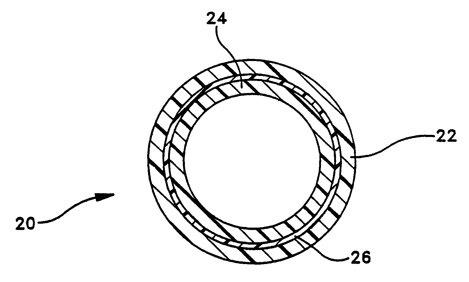
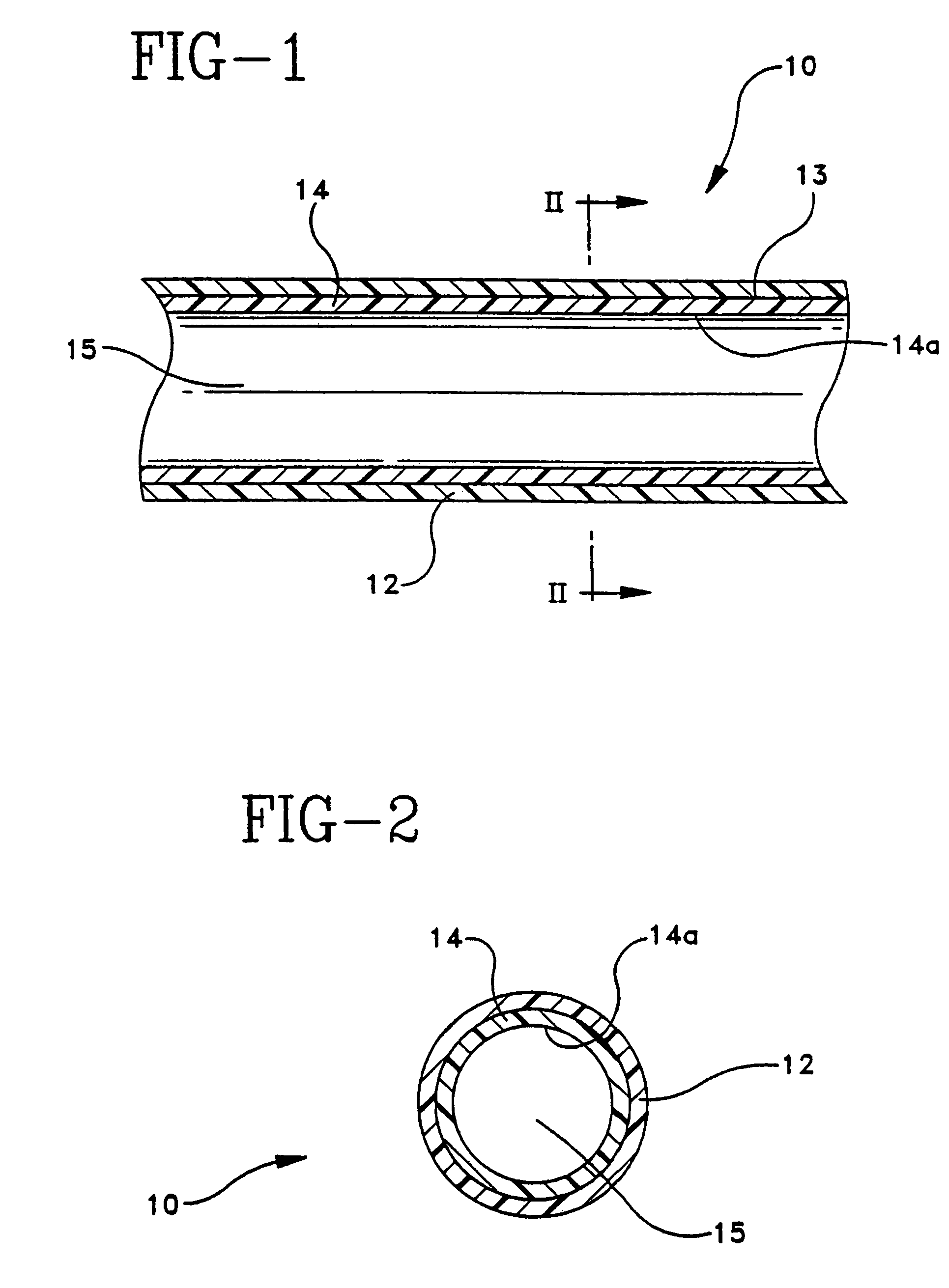
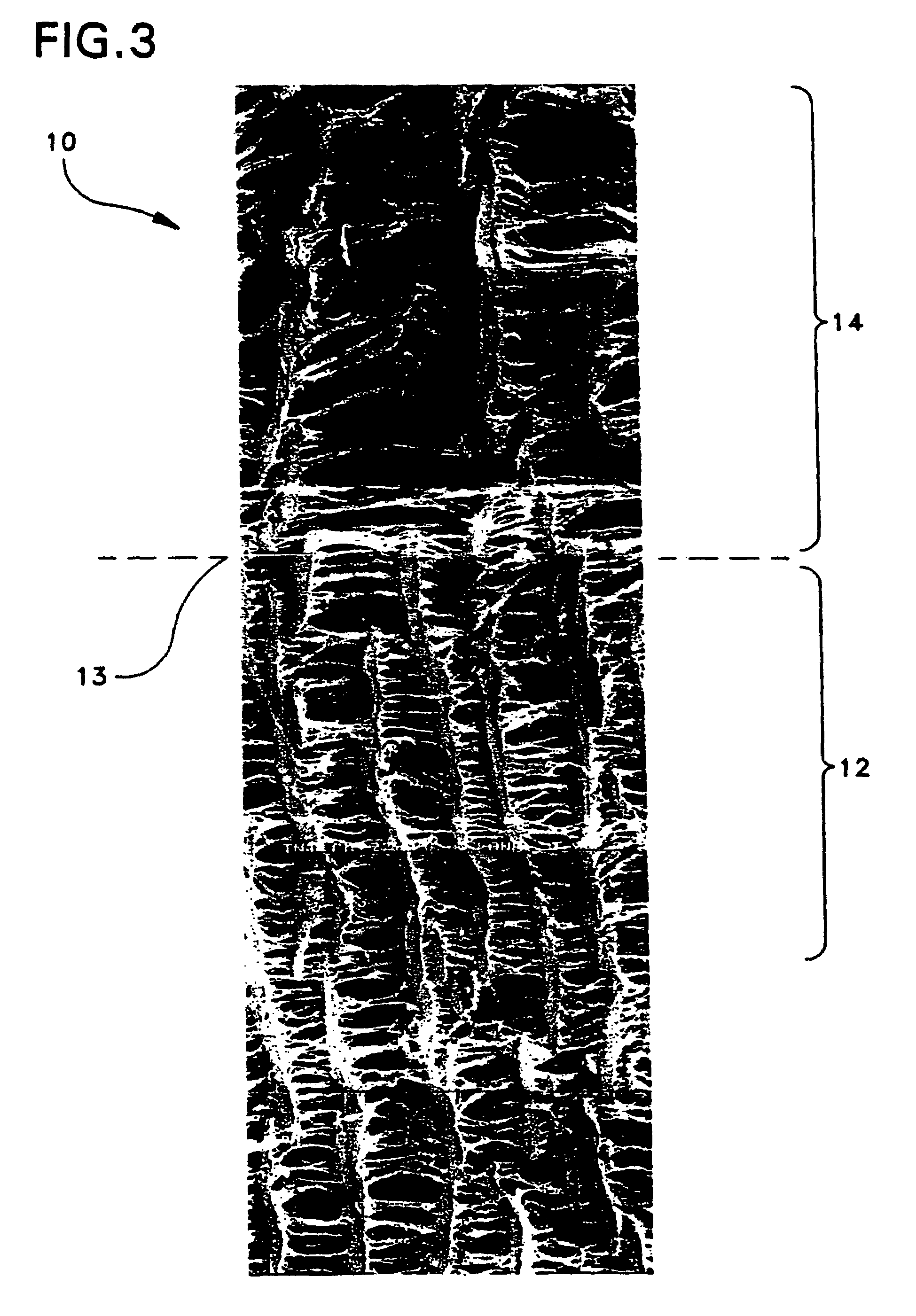
[0060]A thin extruded tube having wall thickness of 0.41 mm and an inner diameter of 6.2 mm was expanded over a stainless steel mandrel at 500° F. to 900% elongation. The ePTFE tube was then sintered at 660° F. for 14 minutes, cooled, and removed from the oven. A second thin extruded tube having wall thickness of 0.45 mm and an inner diameter of 6.9 mm was expanded over the first tube / mandrel combination at 500° F. and 400% elongation. The composite was then sintered at 660° F. for 14 minutes, cooled and removed from the oven. The resultant composite tube had a wall thickness of 0.65 mm and ID of 5.8 mm.

example 2

[0061]A thin extruded tube having wall thickness of 0.41 mm and an inner diameter of 6.2 mm was expanded over a stainless steel mandrel at 500° F. to 700% elongation. The ePTFE tube was then sintered at 660° F. for 14 minutes, cooled, and removed from the oven. A second thin extruded tube having wall thickness of 0.45 mm and an inner diameter of 6.9 mm was expanded over the first tube at 500° F. and 400% elongation. The composite was sintered at 660° F. for 14 minutes, cooled, and removed from the oven. The resultant composite tube had a wall thickness of 0.67 mm and an inner diameter of 5.8 mm.

[0062]Table I presents physical property data for a vascular graft of the type depicted in Example I described above. The composite graft was removed from the mandrel and subjected to standard testing of radial tensile strength and suture hole elongation. The radial strength of the 900% / 400% composite graft is equivalent to a single layer 400% elongation graft and substantially stronger than ...

example 3

[0064]Three composite grafts were constructed and their ability to reseal after a puncture was tested. Graft No. 1 is an ePTFE helically tape-wrapped graft with no resealable layer, and graft Nos. two (2) and three (3) were constructed with a resealable intermediate layer in the below-described procedure.

[0065]Graft No. 1 is an ePTFE graft used as the control in the following experiment. Graft 2 was constructed by first placing an ePTFE tubular structure with an inner diameter of 5 millimeters on a mandrel. A thermoplastic elastomer tubing was then slid over the ePTFE tube. Because of the tackiness of the thermoplastic elastomeric tubing, it was necessary to manipulate the tubing by rolling and stretching it in order to maneuver it over the first ePTFE tubular structure to lie evenly thereon. A second ePTFE tubular structure with an inner diameter of five (5) millimeters was then radially stretched, or expanded to yield an ePTFE tubular structure with an inner diameter of 8 millimet...


PUM

PropertyMeasurementUnit
elongationaaaaaaaaaa

Abstract

An implantable microporous ePTFE tubular vascular graft exhibits long term patency, superior radial tensile strength and suture hole elongation resistance. The graft includes a first ePTFE tube and a second ePTFE tube circumferentially disposed over the first tube. The first ePTFE tube exhibits a porosity sufficient to promote cell endothelization, tissue ingrowth and healing. The second ePTFE tube exhibits enhanced radial strength in excess of the radial tensile strength of the first tube.

Description

CROSS-REFERENCE TO RELATED APPLICATIONS[0001]This application is a continuation of Ser. No. 10 / 212,609, filed on Aug. 5, 2002, now U.S. Pat. No. 6,719,783, which is a continuation of Ser. No. 09 / 525,710, filed on Mar. 14, 2000, now U.S. Pat. No. 6,428,571, which is a continuation-in-part of Ser. No. 09 / 008,265, filed on Jan. 16, 1998, now U.S. Pat. No. 6,036,724, which is a divisional of Ser. No. 08 / 588,052, filed on Jan. 22, 1996, now U.S. Pat. No. 5,800,512, the contents of which are incorporated herein by reference.FIELD OF INVENTION[0002]The present invention relates generally to a tubular implantable prosthesis such as vascular grafts and endoprostheses formed of porous polytetrafluoroethylene. More particularly, the present invention relates to a multi-layered tubular self-sealing graft or endoprosthesis formed from primarily expanded polytetrafluoroethylene.[0003]BACKGROUND OF THE INVENTION[0004]It is well known to use extruded tubes of polytetrafluoroethylene (PTFE) as impla...

Claims


Application Information

Patent Timeline
Patent Type & Authority Patents(United States)
IPC IPC(8): A61F2/06A61L27/16A61L27/50A61L27/56
CPCA61F2/06A61L27/16A61L27/507A61L27/56C08L27/18
Inventor LENTZ, DAVIDHENDERSON, JAMIEDORMIER, EDWARDZDRAHALA, RICHARDLOOMIS, GARYRAKOS, RONALDSOWINSKI, KRZYSZTOF
Owner LIFEPORT SCI
Why Eureka
Try Eureka