Solar energy converter using a solar cell in a shallow liquid-gel layer

a solar cell and liquid gel technology, applied in the direction of photovoltaics, electrical equipment, semiconductor devices, etc., can solve the problems of low-cost electricity extraction efficiency, achieve the effects of enhancing light collection, increasing output current, and increasing operating efficiency

Inactive Publication Date: 2007-07-17
TANAKA KUNIHIDE
View PDF4 Cites 7 Cited by
  • Summary
  • Abstract
  • Description
  • Claims
  • Application Information

AI Technical Summary

Benefits of technology

[0004]Solar cells operating in liquid and / or gel have an increased operating efficiency resulting from two independent physical phenomena, an increase in output current from the solar cells from simply wetting the solar cells, and enhanced collection of light through refraction and inner reflection of light in the liquid. Dielectric liquids and gels are found to increase energy conversion efficiency of n / p junction solar cells and also function as a medium for optical collection. The properties of dielectric liquid or gel permit the construction of a solar cell panel with a suitable geometry for functioning as an optical collector.

Problems solved by technology

One current problem in a solar cell energy conversion system is the efficient extraction of low-cost electricity.

Method used


Image

  • Solar energy converter using a solar cell in a shallow liquid-gel layer
  • Solar energy converter using a solar cell in a shallow liquid-gel layer
  • Solar energy converter using a solar cell in a shallow liquid-gel layer

Examples


Embodiment Construction

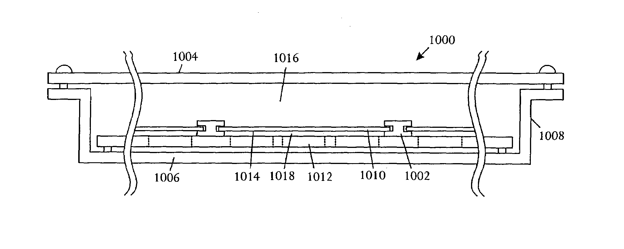
[0021]Referring to FIG. 1, a schematic block diagram depicts an example of a solar panel 100 in a suitable configuration for improving energy conversion efficiency. The solar panel 100 includes a panel base or tray 102 that forms a lower surface wall of the solar panel 100, and panel walls 104 on all sides of the solar panel 100. The solar panel 100 can have any shape. In one set of highly suitable examples, the solar panel 100 has the form of a low height cylindrical structure with the panel tray 102 covering one end of the cylinder and a panel lid 112 covering a second end of the cylinder. All or a portion of the panel walls 104 and the panel lid 112 are transparent to promote functionality as a light collector. The horizontal cross-section of the cylinder can have any suitable shape such as a circle, an ellipse, an oval, an egg-shape, a rectangle, a triangle, and a square. The cross-section of the cylinder can be symmetric or asymmetric. Generally a solar panel 100 with a simple ...


PUM


Abstract

A solar energy converter comprises a thin panel enclosure, at least one solar cell contained within the enclosure, and a thin layer of gel contained within the thin panel enclosure and enclosing the at least one solar cell. The thin panel enclosure has a two-dimensional flat base, short side walls, and a transparent lid separated from the flat base by the short side walls, the short side walls enclosing an interior cavity having a depth substantially smaller than either of the two-dimensional base dimensions. The at least one solar cell has a front surface and a back surface. The thin layer of gel wets both the front surface and back surface of the at least one solar cell and holds the at least one solar cell separate from the base and lid.

Description

CROSS-REFERENCE TO RELATED APPLICATION [0001]The present application is a continuation-in-part of U.S. patent application Ser. No. 10 / 154,668, filed May 22, 2002, entitled “Solar Energy Converter Using A Solar Cell In A Shallow Liquid Layer”, now U.S. Pat. No. 6,583,349 that is a continuation-in-part of U.S. patent application Ser. No. 09 / 887,416, filed Jun. 22, 2001, entitled “Solar Energy Converter Using Optical Concentration Through A Liquid”, now abandoned.BACKGROUND[0002]Solar energy systems have been used to provide electricity and heat for decades. Designers of all types of energy generation systems continually strive to improve output power efficiency. One current problem in a solar cell energy conversion system is the efficient extraction of low-cost electricity. The conversion efficiency of a photovoltaic cell is the proportion of sunlight energy that the cell converts to electrical energy. Improving efficiency is vital to producing solar cells that are competitive with tr...

Claims


Application Information

Patent Timeline
Patent Type & Authority Patents(United States)
IPC IPC(8): H01L31/0203H01L31/048H01L31/042H01L31/052
CPCH01L31/048H01L31/0547H01L31/0543Y02E10/52H02S40/00H02S99/00
Inventor TANAKA, KUNIHIDE
Owner TANAKA KUNIHIDE
Why Eureka
Try Eureka