
Combinations of deflection chopping systems for minimizing energy spreads

a technology of deflection chopping and energy spread, which is applied in the field of construction and use of electrostatic chopping systems, can solve the problems of mechanical chopping not being practicable, reducing the pulse width only to be pushed, and making experimental measurements impractical

Active Publication Date: 2007-07-17
HIGH VOLTAGE ENG EUROPA
View PDF1 Cites 6 Cited by
  • Summary
  • Abstract
  • Description
  • Claims
  • Application Information

AI Technical Summary

Benefits of technology

This configuration improves time compression, allowing for lower energy ion beams to be effectively time-focused, reducing energy spread and increasing beam utilization efficiency, while maintaining stable beam position and angle.

Problems solved by technology

Information can only be impressed on a beam by electromagnetic fields: mechanical chopping is not practical.
While the length of individual pulses can be decreased by increasing the writing speed of the beam across the apertured plate, the resulting reduction in pulse width can only be pushed so far: there is a lower limit of pulse length below which reduction in intensity make experimental measurements impractical.
While this electric field is an essential component needed to produce been sweeping the transverse voltage from which this field is derived has a deleterious effect on the energy spread of ions within each pulse.
This would be true if square waves could be employed for chopping but at frequencies above about a hundred kilohertz square wave deflection voltages are difficult to generate with sufficient amplitude for deflection and sinusoidal voltages derived from a high Q circuit are usually employed.
The phase of the radiofrequency voltages changes during the time an ion passes through the deflection plates and, in general, full cancellation will not be possible.

Method used


Image

  • Combinations of deflection chopping systems for minimizing energy spreads
  • Combinations of deflection chopping systems for minimizing energy spreads
  • Combinations of deflection chopping systems for minimizing energy spreads

Examples


Embodiment Construction

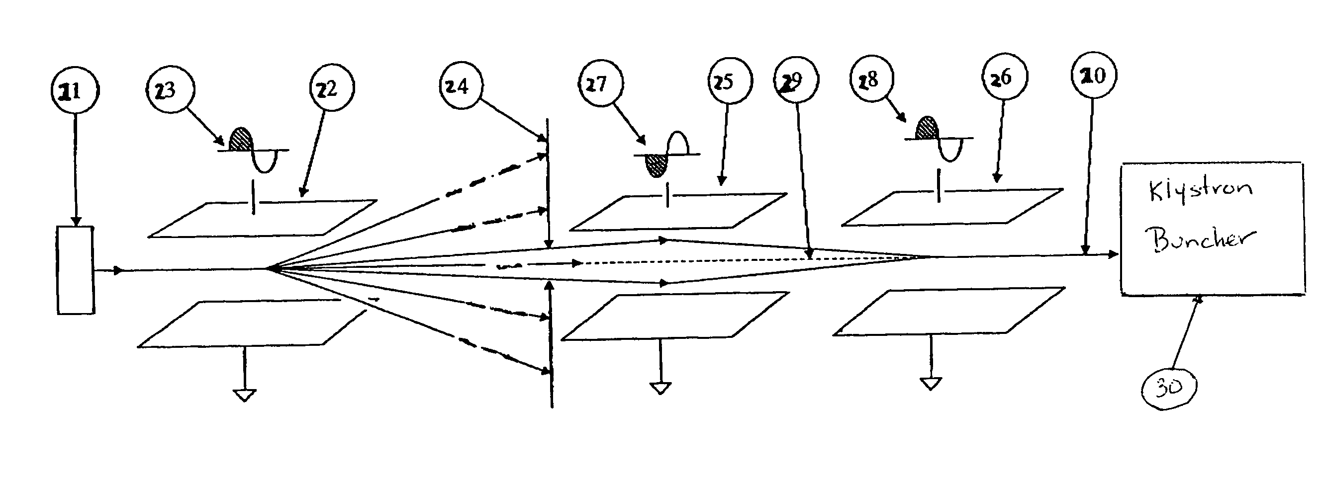
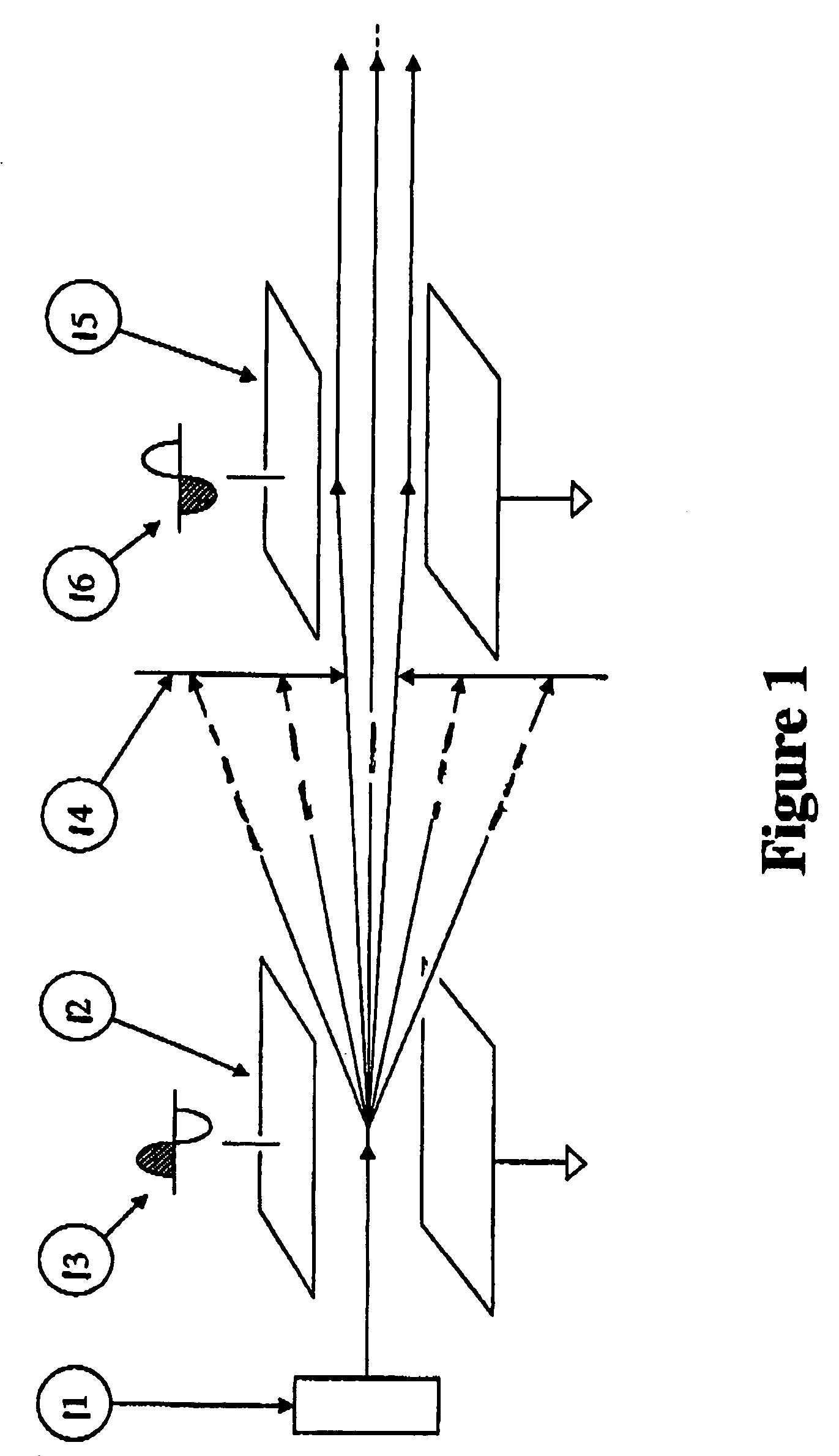
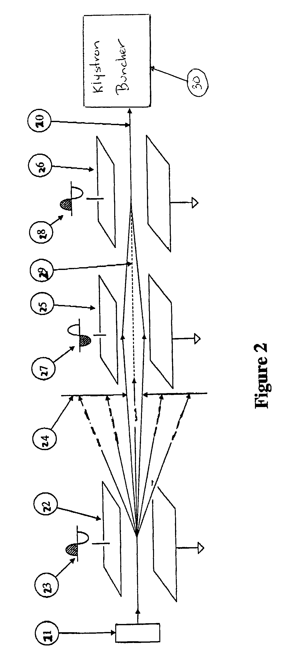
[0028]FIG. 1 presents the preferred embodiment. The first of two deflector units, 12 and 15, is located along the beam path. The chopper, 12, serves to scan the beam leaving ion source, 11, across an aperture plate, 14. Following this plate is located an additional deflector unit, 15. The phase and amplitude of the signals, 16, applied to this second deflector, 15 are adjusted in a manner such that the second deflector, 15, generates an energy modulation of the individual particles, according to equation 2, but with an appropriate phase and amplitude that will cancel the energy spread introduced by the primary chopper, 12. The overall energy spread imposed on the beam by the pair of deflector units, 2 and 5 can be adjusted to be close to zero.

[0029]Referring again to FIG. 1, it can be seen that the first deflector, 12, is excited using a high-voltage radiofrequency whose waveform, 13, is sinusoidal. The effect is to introduce a time-dependent deflection angle to the beam leaving the...


PUM


Abstract

Pulsed MeV ion beam techniques are broadly applied in time-of-flight experiments for direct measurements of neutron velocities and energies. They are also used to achieve a neutron monochromater by allowing the selection of neutrons having a well defined velocity. The sequence of components needed for creation of sub-nanosecond pulsed MeV ion beam systems usually consist of a suitable DC ion source, a chopper module for production of beam pulses, a klystron buncher for introducing time compression to individual pulses and a final ion-acceleration stage. It is pointed out that the achievable pulse compression is limited by the energy spread within the pulses that are directed into the klystron buncher. Furthermore, that this energy spread may be dominated by the energy spread created within the preceding chopper system. The present invention minimizes this problem of chopper introduced energy spreads and discloses a chopping system that comprises at least two electrostatic deflectors with phase-locked radiofrequency voltages. With proper amplitude and phase control chopper assemblies are described that do not add significant energy spreads to the beam.

Description

CROSS REFERENCE AND RELATED APPLICATIONS[0001]This application claims priority to U.S. provisional patent application Ser. No. 60 / 480,862 filed Jun. 24, 2003 entitled “Multiple Deflection Chopping System For Use In Subnanosecond Bunching Systems” the disclosure of which is incorporated herein by reference in its entirety.FIELD OF THE INVENTION[0002]The disclosed methods and apparatus relate generally to the construction and use of electrostatic chopping systems used for producing pulsed beams for time-of-flight measurements and for the injection of ions into radiofrequency accelerators.BACKGROUND TO THE INVENTION[0003]Applications of pulsed MeV beams are conspicuous in the field of experimental nuclear-structure research. Particularly well known is the use of pulsed beams as one component of time-of-flight methods that allow direct measurements of the velocity of neutrons and other particles. This technology also allows the selection of groups of neutrons having well-defined energy ...

Claims


Application Information

Patent Timeline
Patent Type & Authority Patents(United States)
IPC IPC(8): H01J49/44G21K1/087H01J27/02H01J49/40
CPCG21K1/087H01J27/022H01J49/40
Inventor MOUS, DIRK J. W.
Owner HIGH VOLTAGE ENG EUROPA
Learn More