System and method for monitoring and control

a technology of monitoring and control system and monitoring system, applied in the direction of program control, dynamo-electric converter control, motor/generator/converter stopper, etc., can solve the problems of increasing the power consumption of the system, disadvantageous provision of sensors to monitor the system directly, and reducing the performance of the system, so as to reduce the differen

Inactive Publication Date: 2007-07-17
OXFORD UNIV INNOVATION LTD
View PDF30 Cites 14 Cited by
  • Summary
  • Abstract
  • Description
  • Claims
  • Application Information

AI Technical Summary

Problems solved by technology

However, there are situations where the provision of sensors to monitor the system directly is disadvantageous.
This is particularly true where the presence of the sensor can alter the system being monitored, or can degrade its performance, for instance by increasing the power consumption of the system, e.g. by requiring power itself, by introducing friction, or by disturbing the response of the system to an input.
The presence of physical sensors also tends to add complexity to the system, and usually adds mass, and again there are situations where mass is critical and complexity needs to be reduced in order to increase the reliability of the system.
In that situation there is a general desire to reduce power consumption, to reduce mass and to reduce complexity, and so the provision of physical sensors on systems is undesirable.
This is not possible with rotary electric motors.
As mentioned above it is desirable to be able to monitor the state of the system, in this case the linear motor and compressor, and a particular problem in the use of such linear electro-mechanical transducers is the measurement and control of the stroke and offset of the transducer.
Thus, when such a transducer is in sinusoidal motion, its mean position is not easily defined or measured.
This causes a number of problems.
For instance, if the stroke and offset are not carefully controlled, damage can occur if the axial movement of the transducer exceeds the design range because it can result in unintended contact between different components of the system.
However, such monitoring transducers, and their associated electronics add significantly to the size and cost of the device.
The additional complexity also reduces reliability.
However, the assumption that the force developed by the linear motor is directly proportional to the current, (the two being related by a constant known as the electro-mechanical transfer constant) is not correct for typical systems.
That, also, is specific to the particular compressor design illustrated in the patent and is not generally applicable to other applications.
It should also be said that if any of the system parameters of the compressor or linear motor vary, for example because of temperature variation or a fault condition, these cannot be taken into account and the measurements become less accurate or erroneous.
Single compressor units are inherently unbalanced and thus generate vibration.

Method used


Image

  • System and method for monitoring and control
  • System and method for monitoring and control
  • System and method for monitoring and control

Examples


example

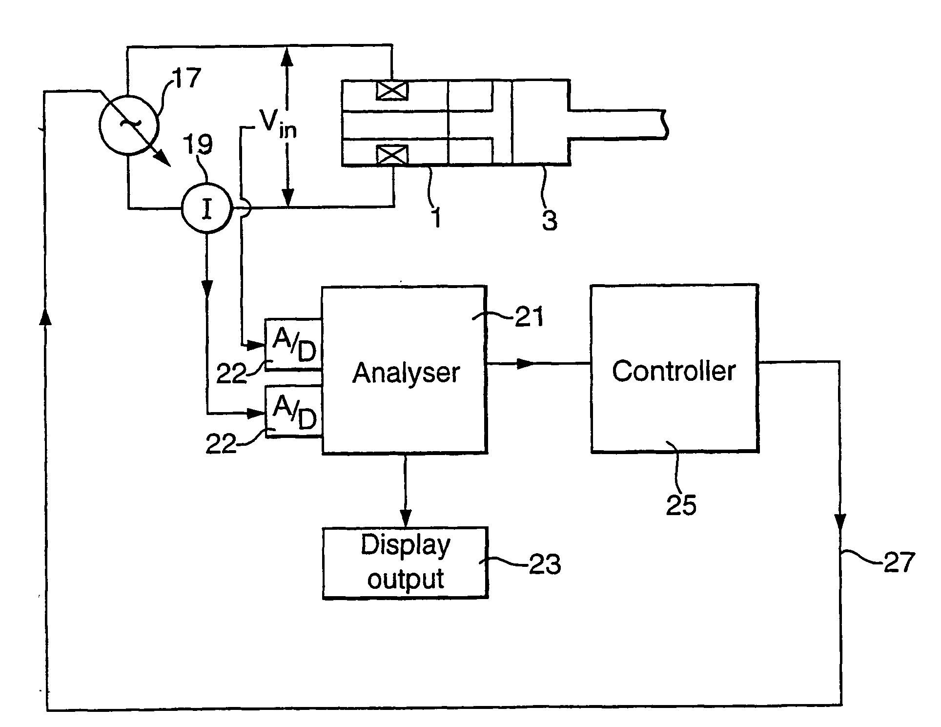
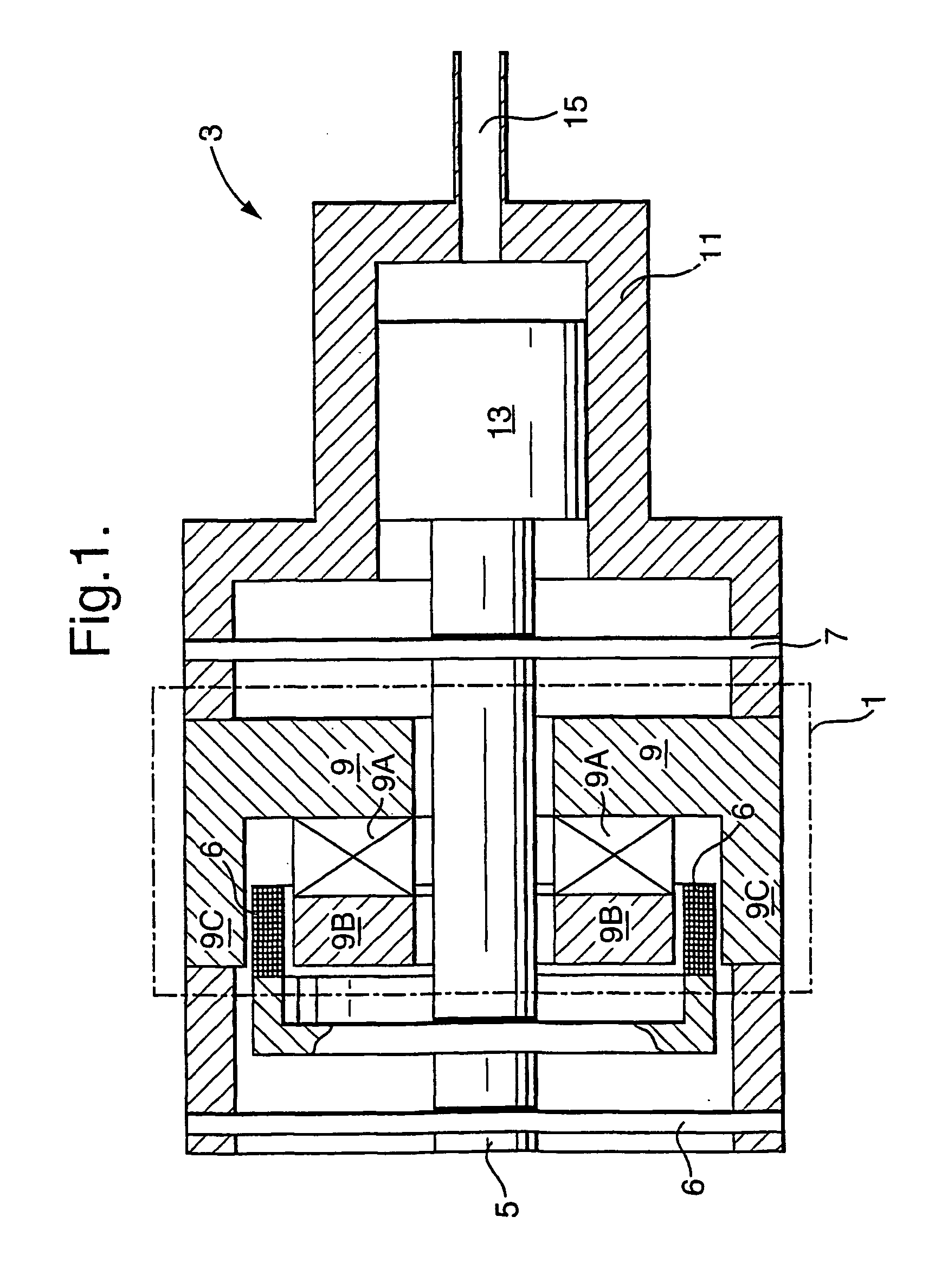
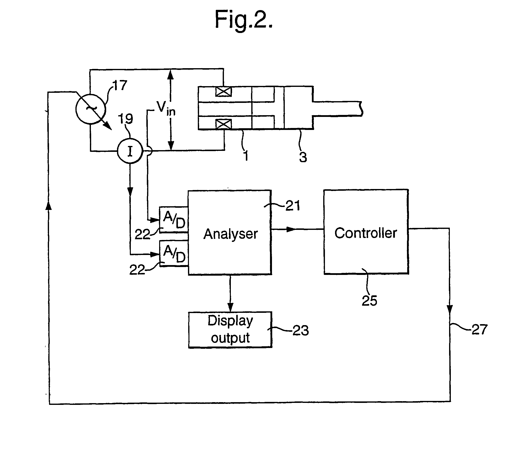
[0105]A specific example illustrating the application of the invention to a moving coil linear motor driving a Stirling cycle cooler (in this case a Hymatic 250 mW Integral Stirling Cycle Cooler—design input power 6 W) will be given below. The equation of motion that has been found to give an accurate model for the particular cooler mentioned above operating at normal design conditions is:

[0106]m⁢ⅆ2⁢xⅆt2+c⁡(x)⁢ⅆxⅆt+kx=F⁡(X,i)=i⁡(t)·G⁡(X)

Where:

[0107]m is the moving mass

[0108]c(x) is a damping coefficient function c(x)=a+b.x.

[0109]k is the spring rate (found to be constant)

[0110]G(X) represents the dependence of coil force on position

[0111]X=x+x0 where x0 is the offset that allows the axial position to be adjusted to give the best model fit.

[0112]G(X) was measured experimentally and is the one shown in graphical form in FIG. 6.

[0113]The equation:

[0114]V⁡(t)+Vdc=E⁡(t)+R·i⁡(t)+L·ⅆiⅆt

represents the electrical behaviour adequately with R and L treated as constants. E(t) can be calculated ...


PUM


Abstract

The invention provides for the monitoring and control of a system, such as a linear electro-mechanical transducer, e.g. a linear electric motor, particularly when driven in a reciprocating manner. A dynamic model of the linear motor and its load is used to calculate from the input drive to the motor a predicted response of the motor. The predicted response is compared to a measured response and the model parameters are varied by global optimisation until the two match as closely as desired. The drive may be the voltage input to the electrical motor and the response may be the electrical current in the motor coils. The parameters and variables of the model, after optimisation, can be taken as good estimates of the actual operating parameters and variables of the linear motor. This gives a measurement of such quantities as the stoke and offset of the linear motor. The invention is particularly applicable to the use of linear motors to drive compressors, for instance in Stirling cycle coolers. The system can be applied to balanced pairs of compressors and to compressor systems which use an active balancer to cancel vibration in the system. In this case a balancer model is created and used in an analogous way to the motor model.

Description

[0001]This application is the U.S. national phase of international application PCT / GB02 / 01782, filed Apr. 17, 2002, which designated the U.S.BACKGROUND AND SUMMARY[0002]The present invention relates to the monitoring and control of systems, in particular to the monitoring of the state of a system in response to an input.[0003]Typically the monitoring of the state of a system, such as a mechanical, electrical, electronic system or combination thereof is achieved by including in the system sensors which are designed to measure and output the value of certain properties, such as operating parameters and variables of the system. The state of the system, and its response to inputs can then be seen in the output of the sensors. However, there are situations where the provision of sensors to monitor the system directly is disadvantageous. This is particularly true where the presence of the sensor can alter the system being monitored, or can degrade its performance, for instance by increasi...

Claims


Application Information

Patent Timeline
Patent Type & Authority Patents(United States)
IPC IPC(8): G05B13/00G05B13/02G05B19/29G05B23/02H02K41/00G05B17/02
CPCG05B17/02G05B23/0254G05B23/0297
Inventor DADD, MICHAEL WILLIAM
Owner OXFORD UNIV INNOVATION LTD
Why Eureka
Try Eureka