Position-sensorless motor control device

a technology of motor control and sensor, which is applied in the direction of motor/generator/converter stopper, electronic commutator, dynamo-electric converter control, etc., can solve the problems of complex processing of extracted signals, and achieve the effect of small computational operation and simple processing

Active Publication Date: 2007-07-17
SANYO ELECTRIC CO LTD
View PDF21 Cites 44 Cited by
  • Summary
  • Abstract
  • Description
  • Claims
  • Application Information

AI Technical Summary

Benefits of technology

[0009]In view of the conventionally experienced inconveniences mentioned above, it is an object of the present invention to provide a position-sensorless motor control device, and a motor drive system incorporating it, that enables position-sensorless control through very simple processing (i.e. with a very small amount of computational operation).
[0010]To achieve the above object, with a first configuration according to the present invention, let the axis parallel to the magnetic flux produced by the permanent magnet forming the rotor of the motor be called the d axis, let the axis estimated, for the purpose of control, to correspond to the d axis be called the γ axis, and let the axis estimated to lead the γ axis by an electrical angle of 90 degrees be called the δ axis, then a position-sensorless motor control device that controls the motor such that the axis error between the d- and γ-axes is reduced is provided with: a superposer that superposes, on the drive current with which the motor is driven, a superposed current having a different frequency than the drive current; a superposed component extractor that extracts, from the motor current fed to the motor, the γ-axis and δ-axis components of the superposed current; and a controller that reduces the axis error by controlling the motor based on the arithmetic product of the γ-axis and δ-axis components of the superposed current.
[0011]With the configuration described above, it is possible to reduce the axis error through very simple processing (i.e. with a very small amount of computational operation).

Problems solved by technology

Disadvantageously, however, according to any of the techniques disclosed in the documents mentioned above, to obtain a signal based on which the rotor position can be estimated, it is necessary to subject the extracted signals to complicated processing; that is, they enable position-sensorless control indeed, but only through complicated processing.

Method used


Image

  • Position-sensorless motor control device
  • Position-sensorless motor control device
  • Position-sensorless motor control device

Examples


first embodiment

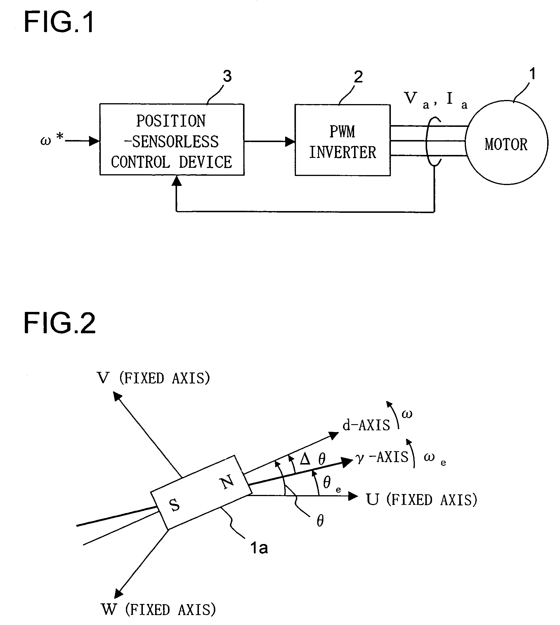
[0050]A first embodiment of the present invention will be described in detail below. FIG. 1 is a block configuration diagram of a motor drive system to which the present invention is applied. Reference numeral 1 represents a three-phase, permanent-magnet, synchronous motor 1 (hereinafter also referred to simply as “motor 1”) that has a permanent magnet on the rotor (unillustrated) thereof and that has an armature winding on the stator (unillustrated) thereof. The motor 1 may be a salient-pole motor (a motor having a salient pole) or a non-salient-pole motor (a motor having no salient pole). The operation with a non-salient-pole motor will be discussed later and until then the following description mainly deals with a case where the motor 1 is a salient-pole motor (for example, an interior-permanent-magnet synchronous motor).

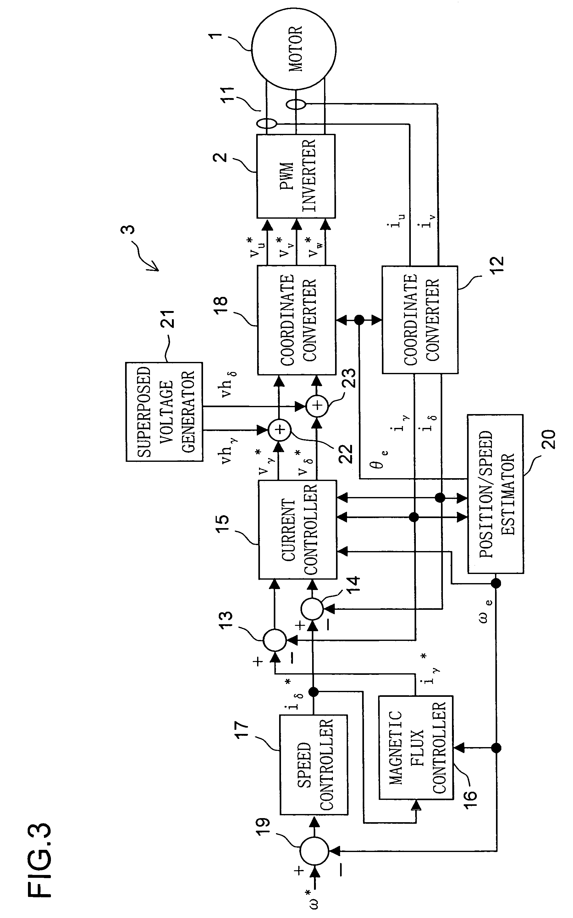
[0051]Reference numeral 2 represents a PWM (pulse-width modulation) inverter, which feeds the motor 1 with a three-phase alternating-current voltage, in U, V, an...

second embodiment

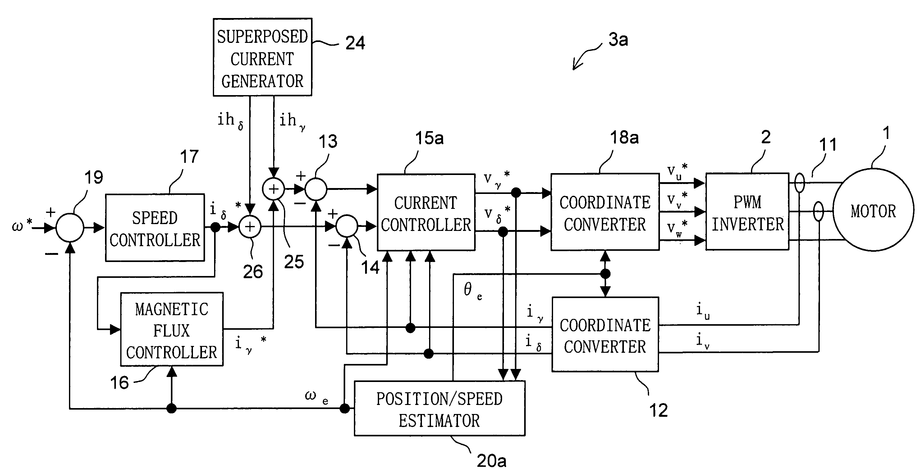
[0097]Next, a second embodiment of the present invention will be described in detail. FIG. 18 is a detailed configuration block diagram of the motor drive system of the second embodiment. The motor drive system of the second embodiment is composed of a motor 1, an inverter 2, and a position-sensorless control device 3a. The position-sensorless control device 3a here differs from the position-sensorless control device 3 shown in FIG. 3 in that the superposed voltage generator 21 and the adders 22 and 23 of the latter are replaced with a superposed current generator 24 and adders 25 and 26, and that the position / speed estimator 20, the current controller 15, and the coordinate converter 18 provided in the latter are replaced with a position / speed estimator 20a (hereinafter also referred to simply as “estimator 20a”), a current controller 15a, and a coordinate converter 18a, respectively. In other respects, the position-sensorless control device 3a here has basically the same configura...


PUM


Abstract

A position-sensorless motor control device has a superposer that superposes, on the drive current with which the motor is driven, a superposed current having a different frequency than the drive current, a superposed component extractor that extracts, from the motor current fed to the motor, the γ-axis and δ-axis components of the superposed current, and a controller that controls the motor so that the direct-current component of the arithmetic product of the extracted γ-axis and δ-axis components of the superposed current converges to zero.

Description

[0001]This application is based on Japanese Patent Application No. 2005-235720 filed on Aug. 16, 2005, the contents of which are hereby incorporated by reference.BACKGROUND OF THE INVENTION[0002]1. Field of the Invention[0003]The present invention relates to a position-sensorless motor control device that drives and controls a motor without the use of a rotor position sensor. The present invention also relates to a motor drive system incorporating such a position-sensorless motor control device.[0004]2. Description of Related Art[0005]There have conventionally been developed techniques for detecting the rotor position of a motor without the use of a sensor. Some of such techniques propose to exploit injection of a high-frequency rotation voltage or a high-frequency rotation current.[0006]For example, JP-A-2003-219682 discloses a technique according to which a high-frequency rotation voltage is applied to a motor, and the rotor position thereof is estimated based on the major-axis di...

Claims


Application Information

Patent Timeline
Patent Type & Authority Patents(United States)
IPC IPC(8): H02P6/08H02P27/00H02P6/18H02P6/06H02P6/17H02P6/182H02P21/00H02P21/22H02P23/16H02P27/04H02P27/08
CPCH02P21/0035H02P21/22
Inventor TOMIGASHI, YOSHIOTAKAO, HIROSHI
Owner SANYO ELECTRIC CO LTD
Why Eureka
Try Eureka