Motor start relay and an electric compressor using same

a technology of motor start relay and electric compressor, which is applied in relays, emergency protective arrangements for limiting excess voltage/current, and positive temperature coefficient thermistor devices. it can solve the problems of the above referenced part and the negative temperature thermistor device subject to the following limitations, and achieves less cost, reduced height or thin motor start relays, and effective short-circuit prevention.

Inactive Publication Date: 2007-07-17
SENSATA TECH MASSACHUSETTS INC
View PDF13 Cites 3 Cited by
  • Summary
  • Abstract
  • Description
  • Claims
  • Application Information

AI Technical Summary

Benefits of technology

[0012]It is an object of the invention to provide a small, low cost motor start relay having a positive temperature thermistor with a failsafe mechanism which is easily assembled.
[0018]Preferably, the top surface of the PTC case is formed with a lip which protrudes into the circular opening at a location generally diametrically opposite to the position of the second contact. When the PTC thermistor is pressed by the spring force of the first and second contacts, the thermistor is biased into engagement with the lip effectively holding that portion of the thermistor along with the first contact. Should the PTC thermistor break, the broken portion aligned with the second contact will be discharged or moved out of the PTC case by the spring force of the second contact. In addition, when the PTC thermistor breaks away, discharge of the said broken portion is abetted by its own weight. By keeping the broken portion away from the remaining portion, possible molten deposition or short-circuiting between the broken elements can be prevented.
[0024]According to this invention, the PTC thermistor is accommodated in a PTC case in which the contact positions of the first and second contact / terminal members are offset from each other, thereby making it possible, when the PTC thermistor is damaged, to discharge a broken portion from the PTC case and effectively prevent short-circuiting that could take place due to molten deposition among the broken portions.
[0025]For the purpose of accommodating the PTC thermistor in the case and realizing a failsafe mechanism by using the PTC case, it is not necessary for the housing itself to directly hold the PTC thermistor. Accordingly, potential choices for the selection of suitable material for the housing to withstand the heat of the PTC thermistor can be expanded. As a result, it becomes possible to make the housing using a heat-resistant resin which is less costly than those used in the past.
[0026]In view of the fact that the PTC thermistor is positioned approximately horizontally in the PTC case and in the housing, it becomes possible to realize a reduced height or thin motor start relay as compared with the conventional structure in which the PTC thermistor is held perpendicularly.
[0027]Due to the arrangement of the first and second contacts, it is not necessary to employ a special tool, thereby improving the efficiency of the assembly work for the motor start relay.

Problems solved by technology

Nevertheless, the positive temperature thermistor device as shown in the above referenced part is subject to the following limitations.

Method used


Image

  • Motor start relay and an electric compressor using same
  • Motor start relay and an electric compressor using same
  • Motor start relay and an electric compressor using same

Examples


Embodiment Construction

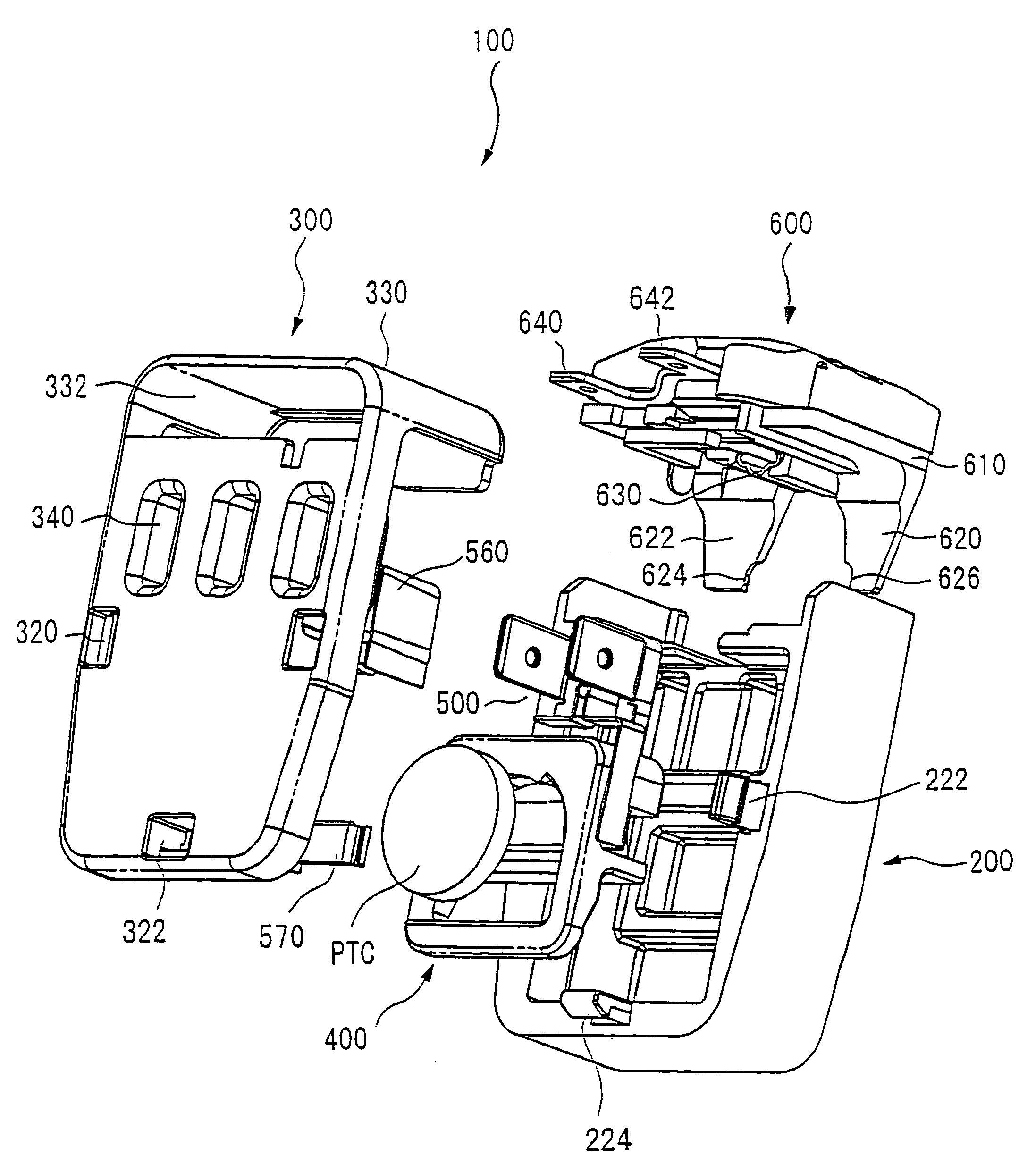
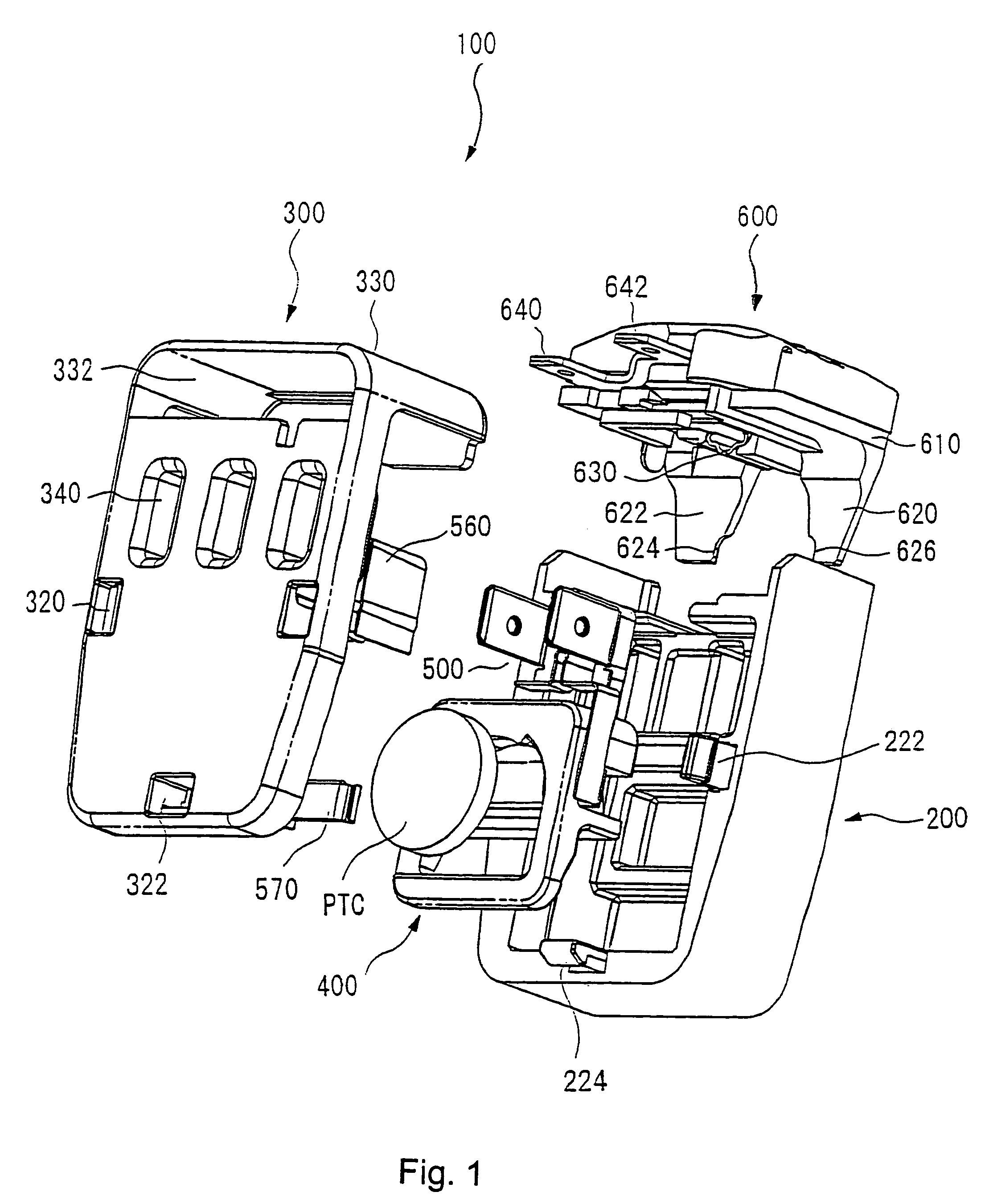
[0052]As shown in FIG. 1, the start relay 100 comprises a housing 200 formed of a thermoplastic and heat-resistant resin such as polybutyrene terephthalate (PBT), a cover 300 formed of like material, a thermistor mounting PTC case 400 formed of suitable material such as a thermoplastic polypheneylene sulfide (PPS) and whose purpose is to accommodate a circular or disc shaped positive temperature coefficient of resistivity thermistor (which will hereafter be abbreviated as PTC thermistor) and a pair of contact / terminal members 500 and 560 which are connected to the PTC thermistor.

[0053]In addition, a protector 600 for opening the circuit to the motor upon overload or over-temperature conditions is removably attached to the motor start relay 100 in this embodiment.

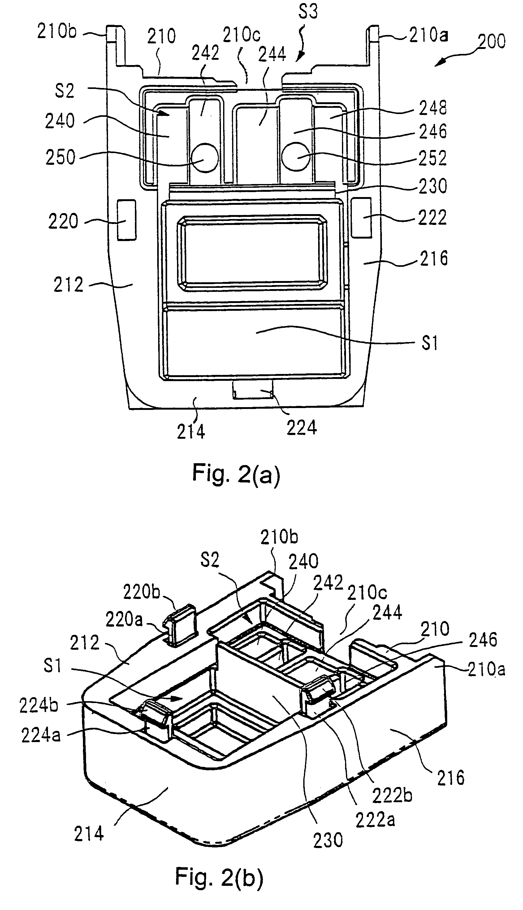
[0054]With reference to FIGS. 2(a), 2(b), housing 200 includes a generally rectangular bottom wall and sidewalls 210, 212, 214 and 216 which extend upwardly therefrom along the outer periphery of the bottom wall forming a ch...


PUM


Abstract

A motor start relay (100) comprises a positive temperature PTC thermistor, a PTC case 400 of heat resistant resin for receiving the PTC thermistor horizontally, first and second contact / terminals (500, 560) each having contacts electrically engaged with a respective electrode surface of the PTC thermistor in the PTC case (400), a housing (200) receiving the PTC case (400) and a cover (300) attached on the housing (200). FIG. 9 shows the failsafe mechanism of the present invention. In case of a crack occurring in the PTC thermistor, thermistor portion PTC1 is rotated by spring contact (510) with a force F1, and thermistor portion PTC2 is pushed by spring contact (570) at the reverse direction and is dropped through an opening of the PTC case (400).

Description

FIELD OF THE INVENTION[0001]This invention relates generally to a motor start relay for starting a single-phase induction motor, or the like, used in electric compressors, or the like and in particular, to such a motor start relay having a failsafe mechanism.BACKGROUND OF THE INVENTION[0002]A motor start circuit to be used in refrigerator or air-conditioner motors is shown in FIG. 11. In that figure, a positive temperature coefficient of resistivity (PTC) thermistor 11 is serially connected with the start winding S of a motor 10 that has a start winding S and a main winding M. An overload protection device 12 is connected to common terminal C of start winding S and main winding M. PTC thermistor 11 has a low resistance at normal ambient temperature when the motor has first been started, with a result that a sufficient amount of start current flows through start winding S to start the motor.[0003]After start-up of the motor, PTC thermistor 11 generates heat due to electric current th...

Claims


Application Information

Patent Timeline
Patent Type & Authority Patents(United States)
IPC IPC(8): H01C7/10H01C7/02H01C1/022H01H45/00H01H45/02H02H9/02H02K11/00
CPCH01C1/022H01H61/002H01H45/00H01H45/02
Inventor OZAWA, KOUICHI
Owner SENSATA TECH MASSACHUSETTS INC
Why Eureka
Try Eureka