
Multiple antenna diversity on mobile telephone handsets, PDAs and other electrically small radio platforms

Inactive Publication Date: 2007-07-17
MICROSOFT TECH LICENSING LLC
View PDF10 Cites 19 Cited by
  • Summary
  • Abstract
  • Description
  • Claims
  • Application Information

AI Technical Summary

Benefits of technology

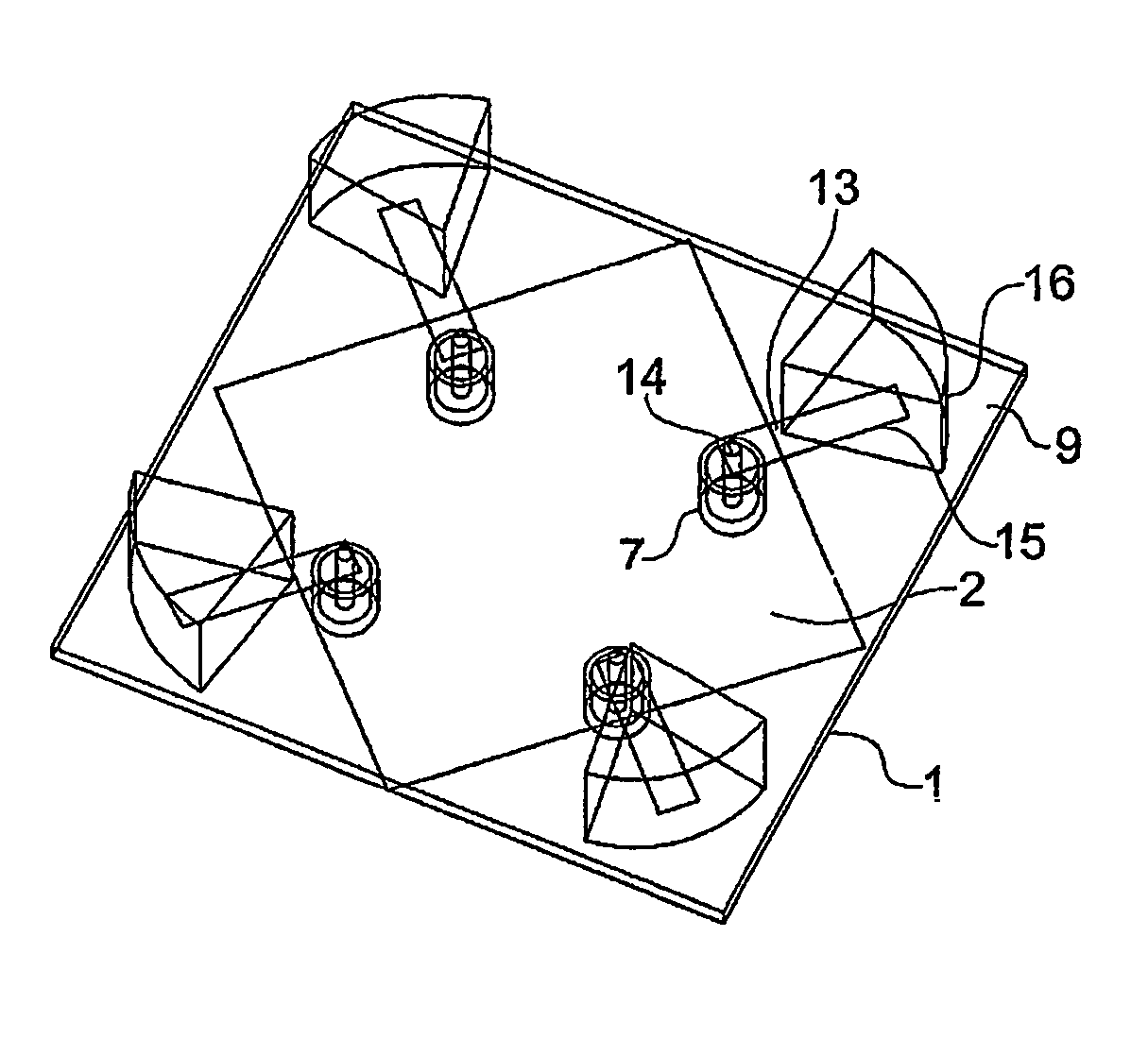
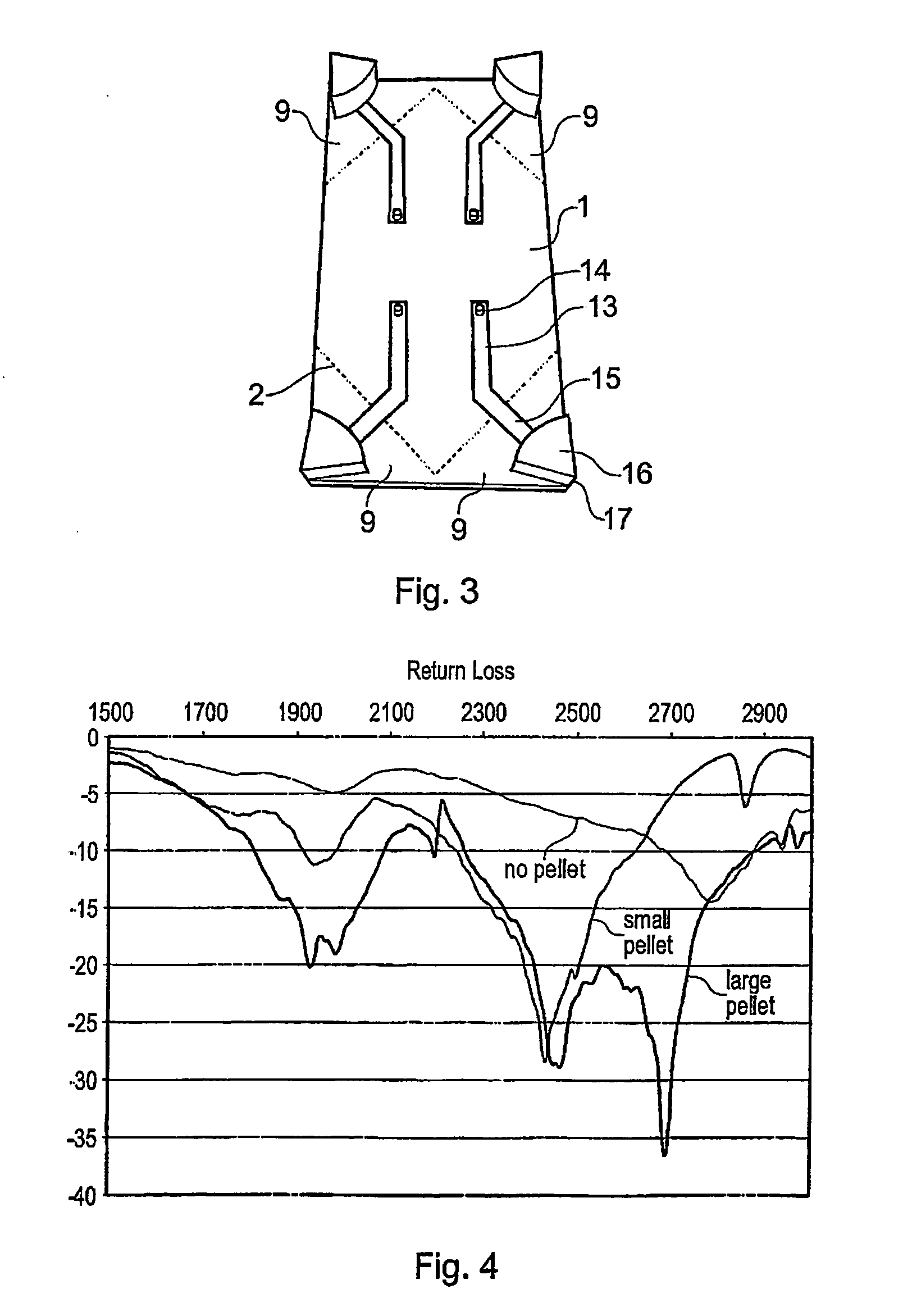
[0023]In general, similar configurations may be provided on any polygonal substrate, for example pentagonal, hexagonal, heptagonal, octagonal and so forth. Indeed, it is not so much the shape of the substrate that is important, but more the relative arrangement of the radiating points and the groundplane. However, given that one aim of embodiments of the present invention is to provide multiple broadband antenna diversity on a small radio platform, it is generally desirable for the substrate to have as mall an area as possible so that it can easily be contained within a small device such as a mobile telephone handset or a WLAN access point. In order to maximise spatial efficiency, the radiating points are advantageously located at corner or edge regions of the first surface of the substrate.
[0024]Notwithstanding the above, consideration of the practical aspects of constructing several diversity antennas on an electrically small platform generally leads to the conclusion that an even number of radiating points is preferable to an odd number, and that a particularly preferred number of radiating points (i.e. individual diversity antennas) is four. One reason for this is that four radiating points / antennas can be arranged to point in four directions mutually at right angles to each other, and coupling between the antennas can thus be reduced. Furthermore, driving the four radiating points / antennas pairwise rather than individually enables greater directivity. Four radiating points / antennas is considered to be especially useful for implementing the BLAST® communication technique developed by Lucent® / Bell Labs® for increasing data communication rates.
[0029]In preferred embodiments, the dielectric elements are soldered or otherwise attached on top of the feedlines in the corner or edge regions of the first surface of the substrate. Alternatively, the ends of the feedlines may be attached to a vertical side surface of the dielectric elements, or even extend on to top surfaces of the dielectric elements. The surfaces of the dielectric elements that contact the ends of the feedlines may be metallised, and in some embodiments at least inwardly facing side surfaces of the dielectric elements may also be metallised so as to improve isolation between the radiating points.

Problems solved by technology

An important problem facing antenna designers, in particular today where many portable appliances such as computers, mobile telephones, computer peripherals and the like communicate with each other in a wireless manner, is to provide good diversity within a small space.
A significant problem arises when diversity is required from a small space or volume such that the antennas have to be closely spaced.
Such high isolation is extremely hard to achieve with conventional antennas when the access points are the size of domestic smoke alarms and less than a wavelength across.
As described in the paper by Wu et al, this type of antenna does not have sufficient bandwidth to be used in a mobile communications system.

Method used


Image

  • Multiple antenna diversity on mobile telephone handsets, PDAs and other electrically small radio platforms
  • Multiple antenna diversity on mobile telephone handsets, PDAs and other electrically small radio platforms
  • Multiple antenna diversity on mobile telephone handsets, PDAs and other electrically small radio platforms

Examples


Embodiment Construction

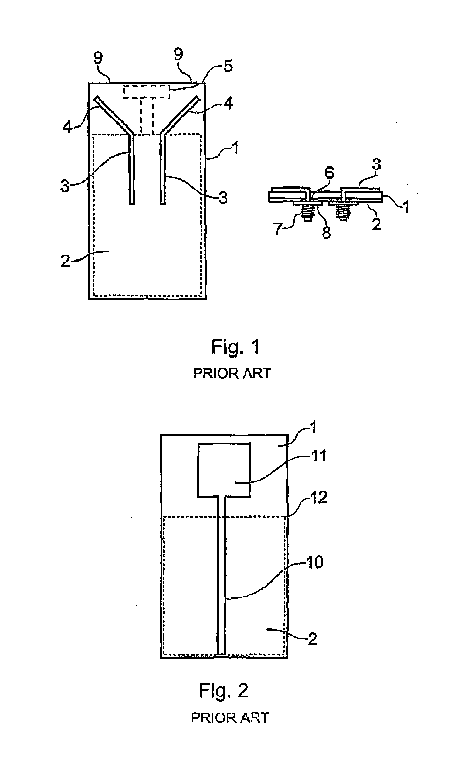
[0048]FIG. 1 shows a prior art printed microstrip dual monopole antenna device, including a dielectric substrate 1 in the form of an FR4 PCB, a main conductive groundplane 2 on the underside of the substrate 1, two printed microstrip lines 3 on the upper side of the substrate 1, the lines 3 terminating in two radiating sections 4, and a small ‘T’-shaped section of groundplane 5 on the underside of the substrate 1 in a location between the two radiating points 4.

[0049]FIG. 1 also shows the device in cross-section, where it can be seen how the two microstrip lines 3 pass from the upper side of the substrate 1 to its lower side through a pair of gaps or holes 6 in the groundplane 2, and terminate in a pair of SMA connectors 7 which are electrically isolated from the groundplane 2 by insulating washers 8.

[0050]The two microstrip lines 3 are configured such that the radiating sections 4 point towards corners 9 of the substrate 1 and air disposed at 90 degrees to each other. No groundplan...


PUM


Abstract

There is disclosed an antenna device including a dielectric substrate having a first, upper surface and a second, lower surface, a conductive groundplane on the second surface or located between the first and second surfaces. At least two conductive feedlines are formed on the first surface and extend from feed points to predetermined radiating points at edge or corner parts of the first surface. The groundplane does not extend under the radiating points. The groundplane is configured as to extend between the radiating points and the feedlines are widened at the radiating points and / or are provided with discrete dielectric elements at the radiating points. The antenna device provides broadband performance and good diversity within a small space.

Description

CROSS-REFERENCE TO RELATED APPLICATION[0001]This Application is a National Phase application of PCT International Application No. PCT / GB2004 / 000511, having an International Filing Date Feb. 9, 2004, and claiming priority of Great Britain Patent Application, 0302818.0, filed Feb. 7, 2003, each incorporated by reference herein in their entirety.FIELD OF THE INVENTION[0002]The present invention relates to techniques for creating multiple antenna diversity on mobile telephone handsets, personal digital assistants and other electrically small radio platforms.BACKGROUND OF THE INVENTION[0003]Various types of antenna devices exist, including dielectric resonator antennas (DRAs), high dielectric antennas (HDAs), dielectrically loaded antennas (DLAs), dielectrically excited antennas (DEAs) and traditional conductive antennas made out of electrically conductive materials.[0004]DRAs are well known in the prior art, and generally are formed as a pellet of a high permittivity dielectric material...

Claims


Application Information

Patent Timeline
IPC IPC(8): H01Q1/38H01Q1/24H01Q9/04
CPCH01Q1/243H01Q1/38H01Q9/0435H01Q9/045H01Q21/28
Inventor PUCKEY, STEVENMARTIN, STEVENPALMER, TIM JOHNKINGSLEY, JAMES WILLIAMKINGSLEY, SIMON PHILIP
Owner MICROSOFT TECH LICENSING LLC
Learn More