Optical waveguide grating coupler

a technology of optical waveguides and couplers, applied in the field of integrated optics, can solve the problems of loss in coupling of optical signals and large differences, and achieve the effect of improving coupling efficiency of optical signals

Active Publication Date: 2007-07-17
CISCO TECH INC
View PDF17 Cites 62 Cited by
  • Summary
  • Abstract
  • Description
  • Claims
  • Application Information

AI Technical Summary

Benefits of technology

[0007]The present invention provides an optical waveguide grating coupler with enhanced efficiency in coupling optical signals in and out of planar waveguide structures.

Problems solved by technology

The disparity in size introduces loss in coupling of the optical signal between the optical fiber and the planar waveguide.

Method used


Image

  • Optical waveguide grating coupler
  • Optical waveguide grating coupler
  • Optical waveguide grating coupler

Examples


Embodiment Construction

)

[0035]Although this invention will be described in terms of certain preferred embodiments, other embodiments that are apparent to those of ordinary skill in the art, including embodiments that do not provide all of the benefits and features set forth herein, are also within the scope of this invention. Accordingly, the scope of the invention is defined only by reference to the appended claims.

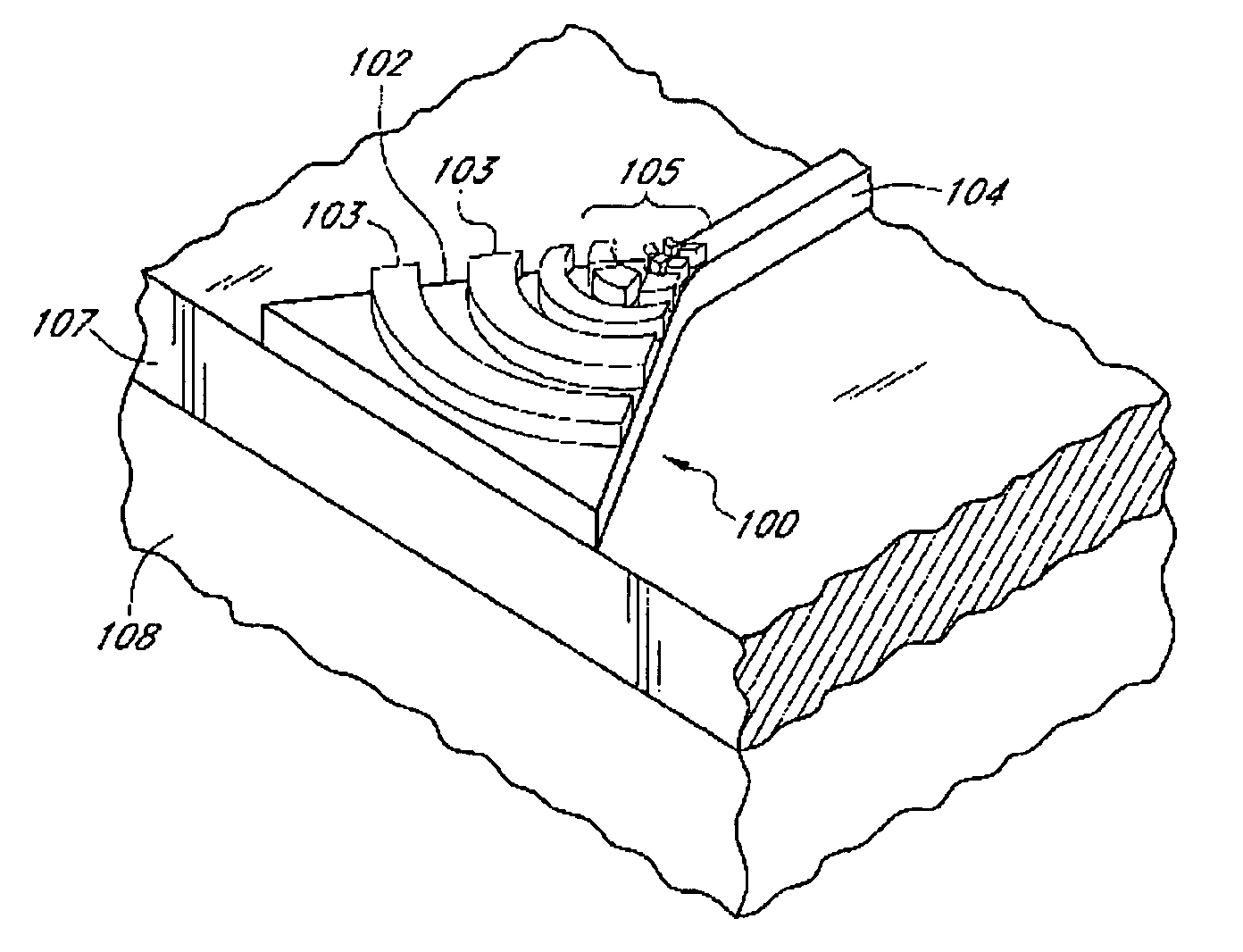
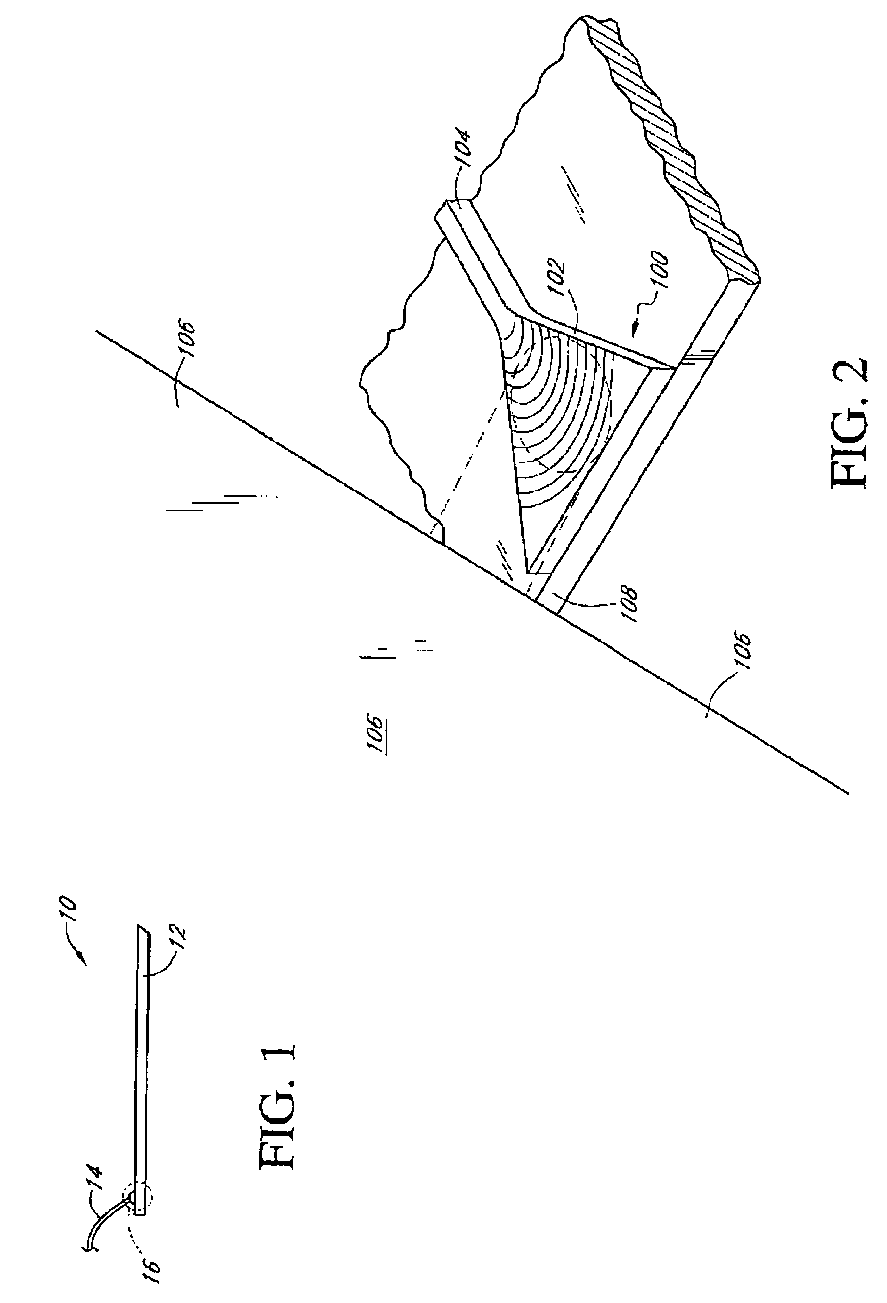
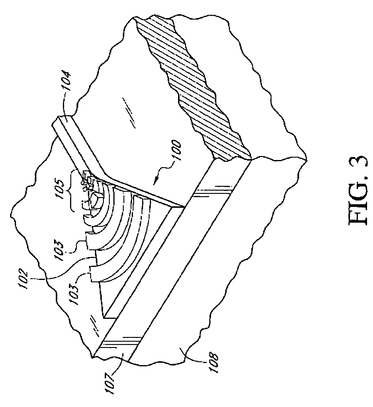
A. Planar Waveguides and Integrated Optical Chips

[0036]In general, optical waveguides comprise a core region comprising material that is at least partially transparent. This core region is surrounded by a cladding region that confines light within the core region. Some optical energy, often referred to as the evanescent energy or the evanescent field, however, may exist outside the core region and within the cladding region.

[0037]In certain waveguides, the core region comprises a first medium having a first refractive index, and the cladding region or cladding comprises a second medium having ...


PUM


Abstract

An optical waveguide grating coupler for coupling light between a planar waveguide and an optical element such as an optical fiber. The optical waveguide grating coupler includes a grating comprising a plurality of elongate scattering elements. The optical waveguide grating coupler is preferably flared, and in various embodiments has hyperbolically shaped sidewalls. The elongate scattering elements are preferably curved, and in some embodiments, the scattering elements have elliptically curved shapes. Preferably, the elongated scattering elements have grating widths selected to accommodate the desired optical intensity distribution.

Description

CROSS REFERENCE TO RELATED APPLICATIONS[0001]This application claims the benefit of U.S. Provisional Applications No. 60 / 446,842, 60 / 446,843, 60 / 446,844, 60 / 446,845, 60 / 446,846 and 60 / 446,847, all of them filed on Feb. 11, 2003.FIELD OF INVENTION[0002]The present invention relates to integrated optics, and more particularly, to an optical waveguide grating coupler for coupling optical signals in and out of integrated optical structures.BACKGROUND OF INVENTION[0003]Light offers many advantages when used as a medium for propagating information, the foremost of which are increased speed and bandwidth. In comparison with electrical signals, signals transmitted optically can be switched and modulated faster and can include an even greater number of separate channels multiplexed together. For these, as well as other reasons, light wave transmission along optical fibers is widespread.[0004]Light can be propagated through planar waveguide structures as well as optical fibers. Planar wavegui...

Claims


Application Information

Patent Timeline
Patent Type & Authority Patents(United States)
IPC IPC(8): G02B6/26G02B6/34G02B6/42G02B6/12G02B6/122G02B6/124G02B6/28G02B6/30
CPCG02B6/1228G02B6/124G02B6/34G02B6/305G02B2006/1213G02B2006/12097
Inventor GUNN, III, LAWRENCE C.PINGUET, THIERRY J.RATTIER, MAXIME J.
Owner CISCO TECH INC
Why Eureka
Try Eureka