Spatial position detection method, information input method, spatial position detection apparatus, and information input apparatus

a technology of position detection and information input, applied in the field of information input method, spatial position detection apparatus, etc., can solve the problems of difficult to construct three-dimensional images of objects, large apparatus structure, and large structure, so as to facilitate the application of position detection for an interface section having various kinds of shapes, the effect of simplifying the apparatus layout and improving the flexibility of the apparatus layou

Inactive Publication Date: 2007-07-24
CANON KK
View PDF21 Cites 84 Cited by
  • Summary
  • Abstract
  • Description
  • Claims
  • Application Information

AI Technical Summary

Benefits of technology

[0019]According to the present invention, by detecting the electromagnetic wave transmitted through the interface section, for example, an electromagnetic wave naturally radiated from an object having a temperature is used to detect a relative position of the object generating the electromagnetic wave with respect to the interface section. Then, based on information on a relative distance or positional relationship between the object generating the electromagnetic wave and the interface section, the operation of an apparatus or the like can be controlled. As a result, the following effects are expected to attain.
[0021]As long as the interface section has the characteristics of transmitting the electromagnetic wave used, it is unnecessary to provide a specific mechanical scanning mechanism for specifying the position of the object in the interface section, thereby allowing miniaturization of the apparatus with ease. For example, when a case of a display device is considered, eliminating the need to provide such a mechanical scanning mechanism maintains the maximum size of a display part that performs information input / output, making it possible to improve the flexibility in the apparatus layout.
[0022]A relative positional relationship between the object and the interface section is calculated, and therefore a shape of the interface section is not necessarily flat. As a result, application to position detection for an interface section having various kinds of shapes is facilitated.
[0023]With the information on the relative position relationship between the object and the interface section, manipulation of the information can be performed, so that the number of mechanical components such as a button and a switch can be reduced significantly, thereby realizing the miniaturization of the apparatus with ease.
[0024]The apparatus operation or the like can also be controlled in response to an action naturally performed by a human body or the environmental conditions around the information input apparatus, thus improving the operability and preventing the malfunction.

Problems solved by technology

However, if each of the infrared images formed using the infrared cameras does not include information on an angle to some extent, it is difficult to construct the three-dimensional image of the object.
To allow each of the infrared images to include angle information, the necessity arises to arrange the infrared cameras spatially, which leads to a problem of making the apparatus structure large.
In the apparatus for detecting the position of the object based on the light reflected by the angle and the intensity of the reflected light by using the LED as described above, a light source driver device needs to be provided separately, and therefore the apparatus also has a problem in that its structure becomes large.
Moreover, in this case, since light has a rectilinear characteristic, there is a problem with flexibility in layout.
For example, it is difficult to arrange the light receiving elements for detecting the object position in an interface section having irregularities or a curved surface.

Method used


Image

  • Spatial position detection method, information input method, spatial position detection apparatus, and information input apparatus
  • Spatial position detection method, information input method, spatial position detection apparatus, and information input apparatus
  • Spatial position detection method, information input method, spatial position detection apparatus, and information input apparatus

Examples


embodiment 1

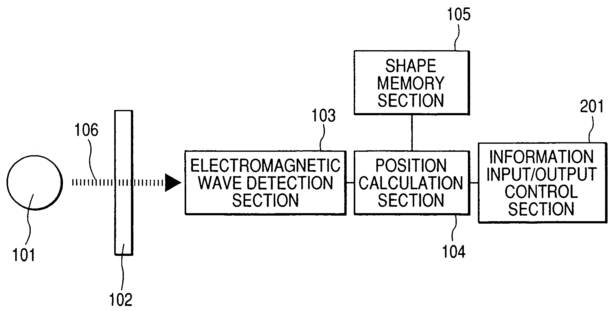
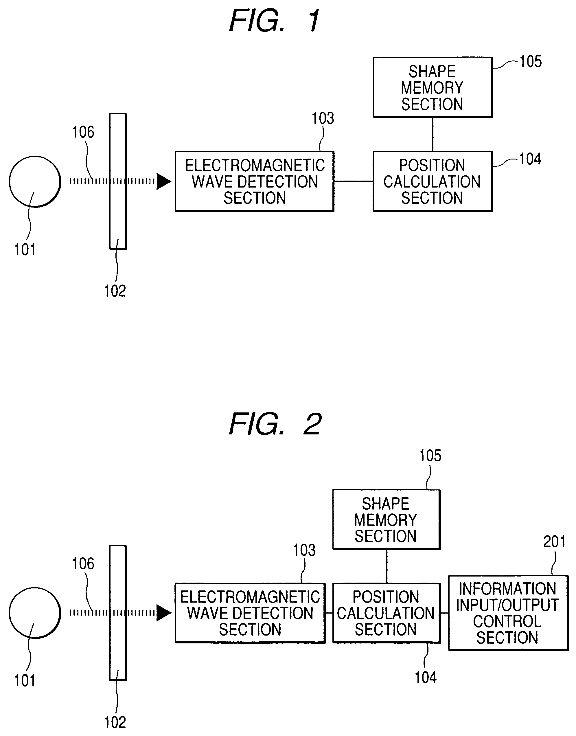
[0073]Here, an adaptation example to a portable information terminal apparatus such as a mobile phone or a mobile computer is described as the above-mentioned information input apparatus. FIG. 12 shows a structure of the portable information terminal apparatus in this embodiment. Here, for convenience of explanation, a mobile phone is used but this embodiment is not limited to this. In this embodiment, a part of a human body is used as each of the objects 101 and a casing of the portable information terminal apparatus is used as the interface section 102. The electromagnetic wave detection section 103, the position calculation section 104, the shape memory section 105, the information input / output control section 201, (and further, the shape memory section 107) which are structural components of the information input apparatus are enclosed inside the casing of the portable information terminal apparatus.

[0074]As described above, the shape memory section 105 stores outer shape inform...

embodiment 2

[0079]Here, there is shown an adaptation example to an information terminal apparatus endowed with a pen input function among portable information terminal apparatuses such as a personal digital assistance (PDA) as the above-mentioned information input apparatus. FIG. 13 shows a structure of the information terminal apparatus endowed with the pen input function of this embodiment. A pen radiating the electromagnetic wave 106 is used as the object 101 in this embodiment. Used as the interface section 102 is a casing of the information terminal apparatus endowed with the pen input function. Components constituting the information input apparatus, namely, the electromagnetic wave detection section 103, the position calculation section 104, the shape memory section 105, and the information input / output control section 201 (and further, the physical property information memory section 107) are enclosed inside the casing of the information terminal apparatus endowed with the pen input fun...

embodiment 3

[0084]Here, there is shown an adaptation example to a television set, a personal computer, and other display devices having a touch panel as the above-mentioned information input apparatus. FIG. 14 shows a structure of the information terminal apparatus endowed with the touch panel input function added to the television set as the display device of this embodiment. A part of a human body is used as the object 101 in this embodiment. Used as the interface section 102 is a display of the television set. Components constituting the information input apparatus, including the electromagnetic wave detection section 103, the position calculation section 104, the shape memory section 105, the information input / output control section 201 (and further, the physical property information memory section 107) are enclosed inside the casing of the display device.

[0085]As described above, the shape memory section 105 stores outer shape information of the casing in advance. Furthermore, as in this e...


PUM


Abstract

To calculate information on a relative distance or positional relationship between an interface section and an object by detecting an electromagnetic wave transmitted through the interface section, and using the electromagnetic wave from the object to detect a relative position of the object with respective to the interface section. Information on the relative spatial position of an object 101 with respect to an interface section 102 that has an arbitrary shape and deals with transmission of information or signal from one side to the other side of the interface section 102 is detected with a spatial position detection method. An electromagnetic wave 106 radiated from the object 101 and transmitted through the interface section 102 is detected by an electromagnetic wave detection section 103, and based on the detection result, information on spatial position coordinates of the object 101 is calculated by a position calculation section 104.

Description

TECHNICAL FIELD[0001]The present invention relates to a spatial position detection method and apparatus for finding out information on a spatial position of an object radiating an electromagnetic wave by using an electromagnetic wave transmitted through an interface section, and an information input method and apparatus for, after detection of information on a positional relationship between the object and the interface section, processing the information in accordance with a predetermined interpretation method and controlling an operation of an apparatus and input states of information or a signal.BACKGROUND ART[0002]As a spatial position detection apparatus, there is exemplified a three-dimensional position detection apparatus which forms images based on infrared rays radiated from a human body by using plural infrared cameras and calculates center coordinates of the human body based on the detected images to detect a position of the human body (JP 07-035842 A). In addition, anoth...

Claims


Application Information

Patent Timeline
Patent Type & Authority Patents(United States)
IPC IPC(8): G06F19/00G06F3/046G01S5/02G01S11/02G06F3/041G06F3/042
CPCG06F3/042
Inventor ITSUJI, TAKEAKIOUCHI, TOSHIHIKO
Owner CANON KK
Why Eureka
Try Eureka