Procedure for starting up a fuel cell system having an anode exhaust recycle loop

a fuel cell and recycle loop technology, applied in the direction of fuel cells, solid electrolyte fuel cells, fuel cells, etc., can solve the problems of increasing the number of start/stop cycles, rapid performance decay of the cell stack assembly, etc., and achieve the effect of increasing the fuel flow ra

Inactive Publication Date: 2007-07-31
AUDI AG
View PDF3 Cites 5 Cited by
  • Summary
  • Abstract
  • Description
  • Claims
  • Application Information

AI Technical Summary

Benefits of technology

[0008]Preferably an auxiliary resistive load is connected across the cell as the oxygen is being consumed to reduce the cell voltage during the process. The use of a diffusion burner and separate catalytic burner in the recycle loop, or a catalytic burner alone, is also advantageous to speed up the removal of oxygen.
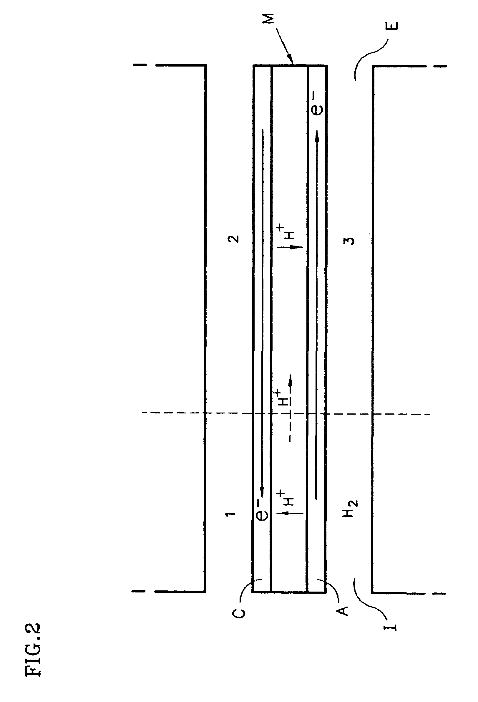
[0013]The flow of electrons from the portion of the anode that sees hydrogen to the portion of the anode that sees air results in a small change in the potential of the electron conductor. On the other hand, electrolytes in the membrane are relatively poor in-plane proton conductors, and the flow of protons results in a very significant drop in the electrolyte potential between zones H2 and 3.
[0015]One object of the present invention is to minimize fuel cell catalyst and catalyst support corrosion occurring during start-up of the fuel cell, and to do it without purging air from the cells with inert gas upon start-up.
[0017]Since only a mixture of air and a limited amount of hydrogen enter the anode flow field during the start-up procedure described above, there is no distinct hydrogen / air front traversing the anode flow field; and there is never a time when one region of the anode sees only hydrogen and the other sees only air. Thus, the high cathode potentials that cause catalyst and catalyst support corrosion are avoided.
[0019]During start-up the recirculating gas stream is partially vented (e.g. a small portion of the recirculating stream leaves the system through a vent valve) to maintain the stream at substantially ambient pressure. This also keeps the nitrogen concentration low, and eliminates any need to purge the recycle loop with hydrogen before the primary load can be connected across the cell.
[0021]Preferably, each burner includes a diffusion burner upstream of and in series with the catalytic burner element, and preferably integrated within the same housing. The diffusion burner includes an igniter that is used to initiate the diffusion burning of the air and hydrogen entering the diffusion burner. The diffusion burning process speeds up the start-up process by more quickly consuming the oxygen in the recycle stream (as compared to catalytic burning alone); however, diffusion burning alone is not as effective as catalytic burning for removing the oxygen to the levels required of the present invention. The combination of the two provide the desired speed and substantially complete removal of the oxygen. The flammability limits, which, as discussed above, should be observed for safety within the fuel cell system, obviously do not apply to the diffusion burner; however, the flammability limits should be observed with regard to the gas composition leaving the diffusion burning zone.

Problems solved by technology

It was found that a cell stack assembly operated in this manner experienced rapid performance decay which had not previously been observed.
Further, it was discovered that a large number of start / stop cycles were more detrimental to cell performance than were a large number of normal operating hours under load.

Method used


Image

  • Procedure for starting up a fuel cell system having an anode exhaust recycle loop
  • Procedure for starting up a fuel cell system having an anode exhaust recycle loop
  • Procedure for starting up a fuel cell system having an anode exhaust recycle loop

Examples


Embodiment Construction

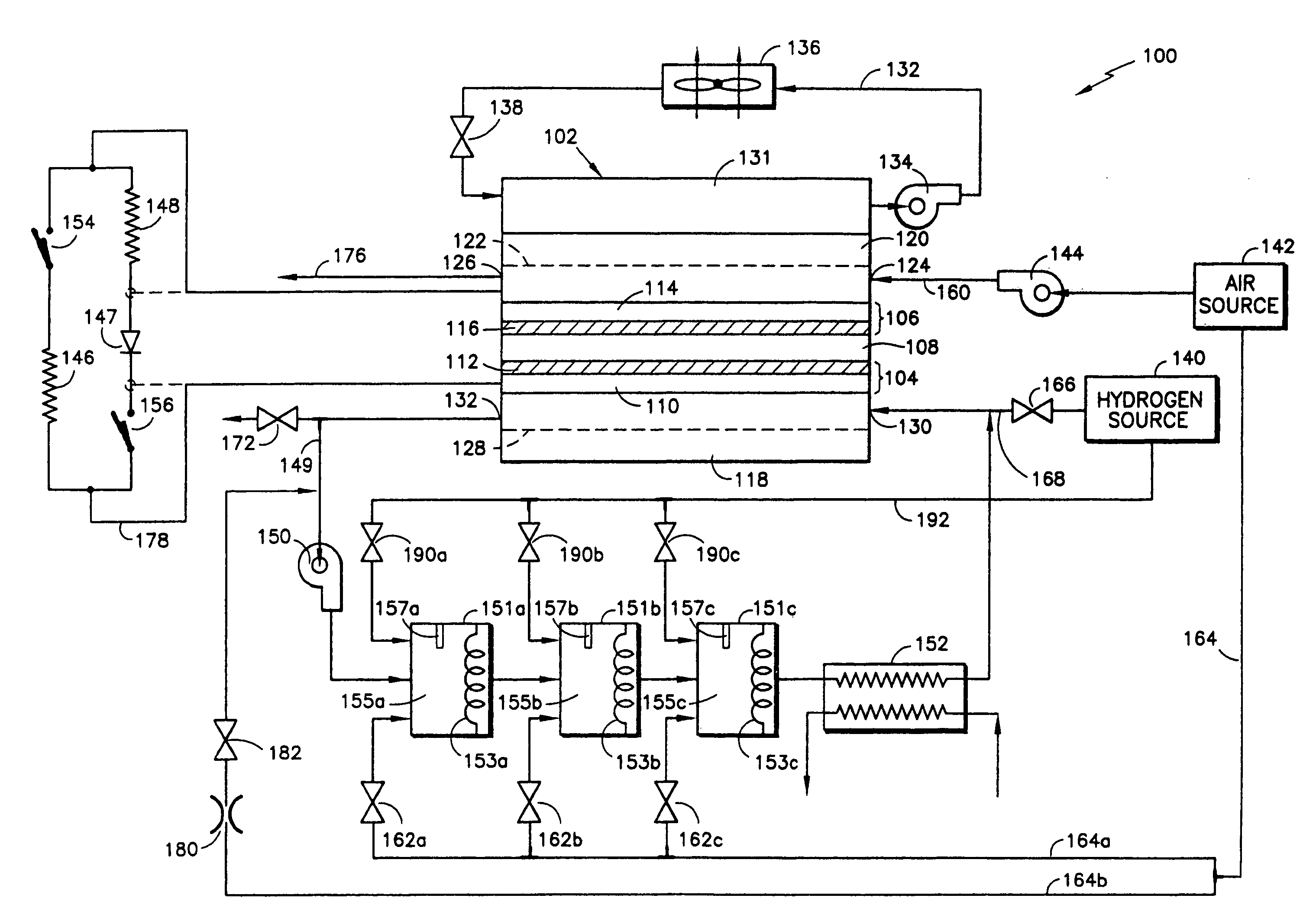
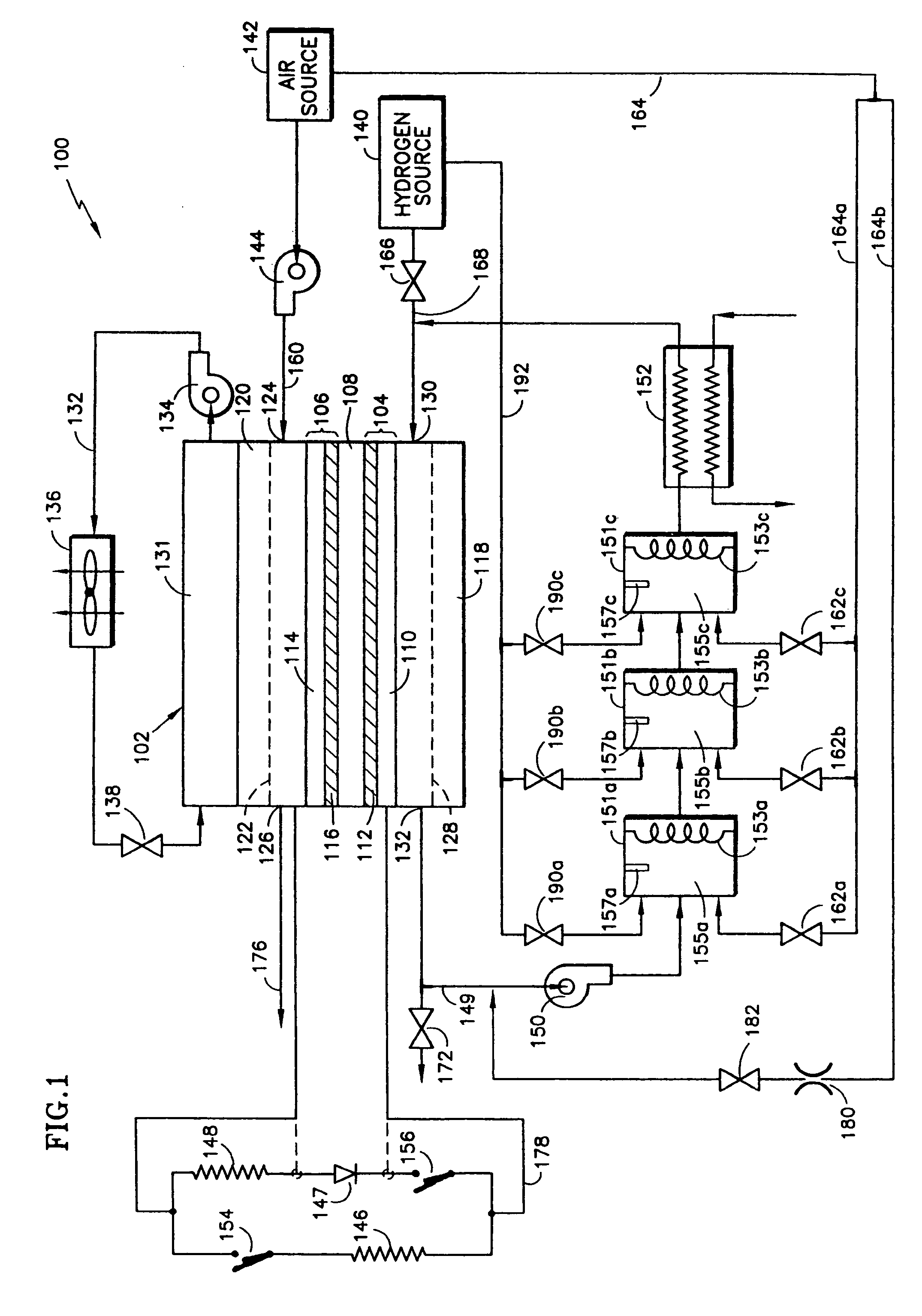
[0027]In FIG. 1, a fuel cell system 100 is shown. The system includes a fuel cell 102 comprising an anode 104, a cathode 106, and an electrolyte layer 108 disposed between the anode and cathode. The anode includes an anode substrate 110 having an anode catalyst layer 112 disposed thereon on the side of the substrate facing the electrolyte layer 108. The cathode includes a cathode substrate 114, having a cathode catalyst layer 116 disposed thereon on the side of the substrate facing the electrolyte layer 108. The cell also includes an anode flow field plate 118 adjacent the anode substrate 110 and a cathode flow field plate 120 adjacent the cathode substrate 114.

[0028]The cathode flow field plate 120 has a plurality of channels 122 extending thereacross adjacent the cathode substrate forming a cathode flow field for carrying an oxidant, preferably air, across the cathode from an inlet 124 to an outlet 126. The anode flow field plate 118 has a plurality of channels 128 extending there...


PUM

PropertyMeasurementUnit
operating flow rateaaaaaaaaaa
voltageaaaaaaaaaa
flammabilityaaaaaaaaaa

Abstract

A procedure for starting up a fuel cell system that is disconnected from its primary load and that has air in both its cathode and anode flow fields includes a) connecting an auxiliary resistive load across the cell to reduce the cell voltage; b) initiating a recirculation of the anode flow field exhaust through a recycle loop and providing a limited flow of hydrogen fuel into that recirculating exhaust; c) catalytically reacting the added fuel with oxygen present in the recirculating gases until substantially no oxygen remains within the recycle loop; disconnecting the auxiliary load; and then d) providing normal operating flow rates of fuel and air into respective anode and cathode flow fields and connecting the primary load across the cell. The catalytic reaction may take place on the anode or within a catalytic burner disposed within the recycle loop. The procedure allows start-up of the fuel cell system without the use of an inert gas purge while minimizing dissolution of the catalyst and corrosion of the catalyst support during the start-up process.

Description

[0001]This application is a continuation of U.S. patent application Ser. No. 10 / 189,696, filed Jul. 3, 2002, now abondoned which is a continuation of PCT application Ser. No. PCT / US02 / 00078 filed Jan. 4, 2002, which is a continuation of U.S. patent application Ser. No. 09 / 769,897, filed Jan. 25, 2001, now abandoned, the contents of which are incorporated by reference.BACKGROUND OF THE INVENTION[0002]1. Technical Field[0003]This invention relates to fuel cell systems and, more particularly, to procedures for starting up a fuel cell system.[0004]2. Background Information[0005]It is well known in the fuel cell art that, when the electrical circuit is opened and there is no longer a load across the cell, such as upon and during shut-down of the cell, the presence of air on the cathode, coupled with hydrogen fuel remaining on the anode, often cause unacceptable anode and cathode potentials, resulting in catalyst and catalyst support oxidation and corrosion and attendant cell performance ...

Claims


Application Information

Patent Timeline
Patent Type & Authority Patents(United States)
IPC IPC(8): H01M8/06H01M8/10H01M8/04
CPCH01M8/04097H01M8/04223H01M16/003H01M8/04007H01M8/04022H01M8/04231H01M8/04238Y02E60/50H01M8/241H01M8/04225H01M8/04302H01M8/2457H01M8/0258
Inventor YANG, DELIANGSTEINBUGLER, MARGARET M.SAWYER, RICHARD D.VAN DINE, LESLIE L.REISER, CARL A.
Owner AUDI AG
Why Eureka
Try Eureka