Magnetic sensor
a technology of magnetic sensor and sensor body, which is applied in the field of magnetic sensor, can solve the problems of reducing detection accuracy, increasing the size of magnetic sensor b>50/b>, and complicating the fabrication process, so as to reduce the size and improve the detection accuracy
- Summary
- Abstract
- Description
- Claims
- Application Information
AI Technical Summary
Benefits of technology
Problems solved by technology
Method used
Image
Examples
first embodiment
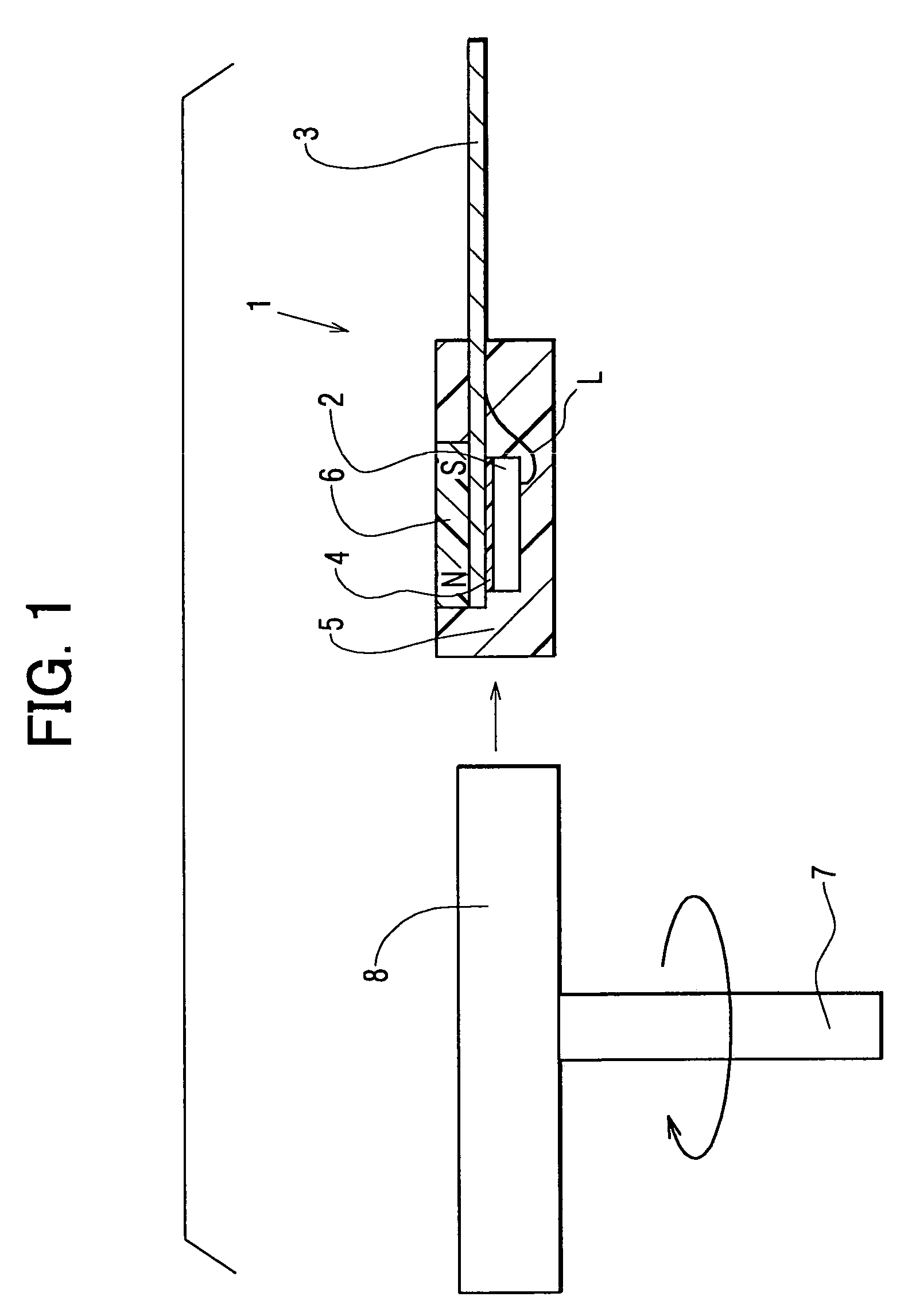
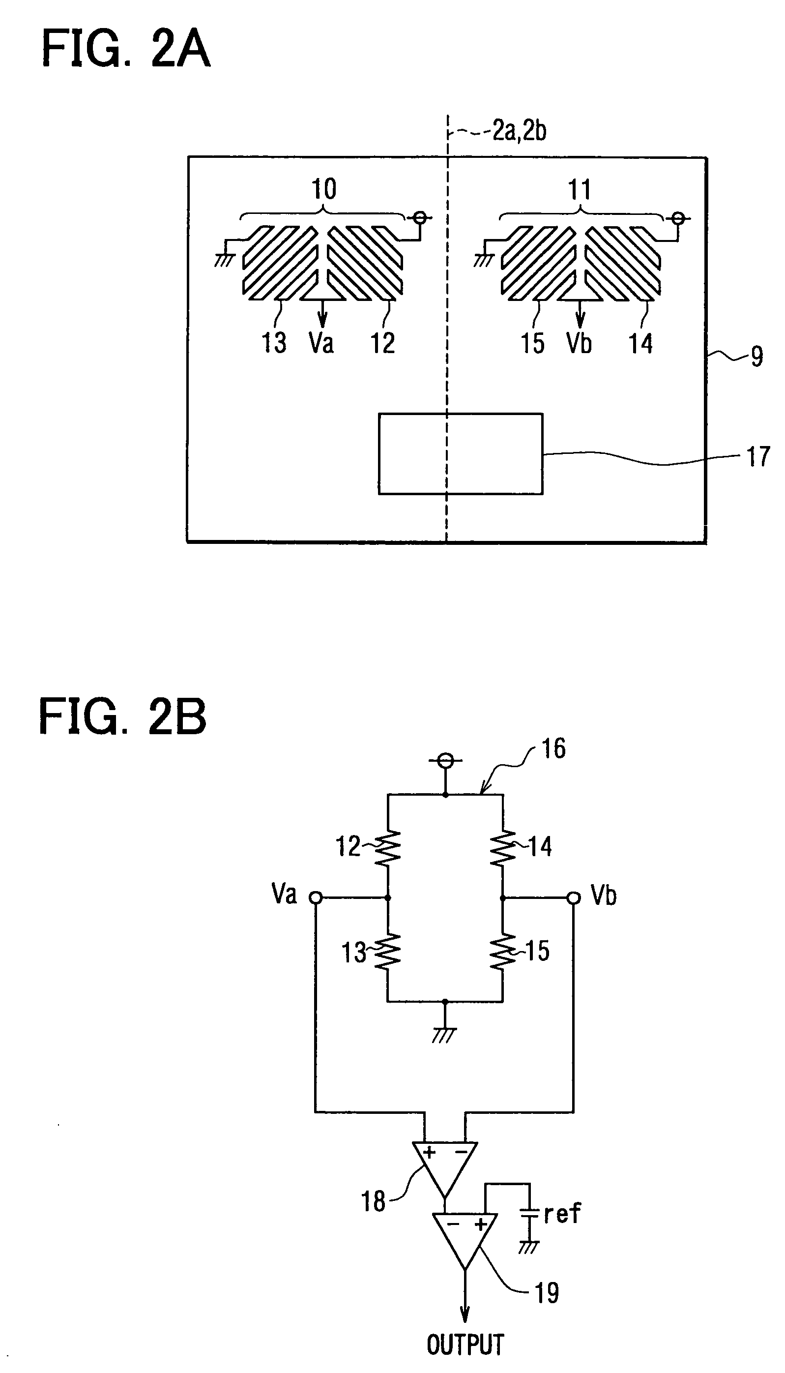
[0036]Now, the present invention will be described with reference to the accompanying drawings in accordance with a magnetic sensor according to a first embodiment. FIG. 1 is a cross-sectional view of a magnetic sensor and a magnetic rotor (an object to be detected) according to the first embodiment of the present invention. FIG. 2A is a plan view of the magnetic sensor chip according to the first embodiment of the present invention, while FIG. 2B is a circuit diagram of the circuit configuration of a magnetoresistive pattern according to the first embodiment of the present invention.
[0037]This embodiment provides a magnetic sensor 1 which can be employed as a rotation detector, for detecting the rotation of a rotating object (including gears) to be sensed, such as an engine rotation sensor, a cam angle sensor, a crank angle sensor, an automobile speed sensor, an AT sensor, and a wheel speed sensor. Referring to FIG. 1, on the right hand side of a gear-shaped (its teeth not shown) m...
second embodiment
[0055]Now, the present invention will be explained with reference to FIG. 6A, FIG. 6B and FIG. 6C, in accordance with a second embodiment. The portions of the second embodiment common to those of the first embodiment are not to be explained in detail. This embodiment is different from the first embodiment in that the bias magnet 6 is formed at a portion on a side of the magnetic sensor chip 2.
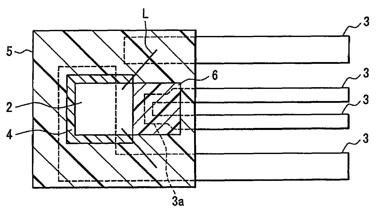
[0056]A method according to this embodiment makes use of the property that a magnetic material is less magnetized when its Curie temperature is reached, thereby being readily affected externally. To reach the Curie temperature, the lead frame 3 is provided with a heat-generating portion 3a, which is part of the lead frame 3 reduced in shape to have an increased resistance and generates heat by a large current flowing therethrough. This heat-generating portion 3a is formed, within the lead frame 3, near the optimal position at which the aforementioned bias magnet 6 is desirably formed as shown, ...
third embodiment
[0059]Now, the present invention is explained with reference to FIG. 7 in accordance with a third embodiment. The portions of the third embodiment common to those of the aforementioned embodiments will not be explained in detail. This embodiment is different from the aforementioned embodiments in that the bias magnet 6 is formed in the lead frame 3.
[0060]A method according to this embodiment includes the step of using a magnetized yoke to magnetize the optimal position desired to form the aforementioned bias magnet 6 in the lead frame 3 made of known copper or b 42Ni—Fe or the like, thereby forming the bias magnet 6. In this manner, the lead frame 3 is employed as the bias magnet 6. Thus, a conventionally available lead frame 3 can be used to form the bias magnet 6 without mixing magnetic powder into the molded material 5, thereby facilitating manufacture.
PUM
| Property | Measurement | Unit |
|---|---|---|
| magnetic-field | aaaaa | aaaaa |
| heat-resistant | aaaaa | aaaaa |
| resistance | aaaaa | aaaaa |
Abstract
Description
Claims
Application Information
 - R&D
- Intellectual Property
- Life Sciences
- Materials
- Tech Scout
- Unparalleled Data Quality
- Higher Quality Content
- 60% Fewer Hallucinations
Browse by: Latest US Patents, China's latest patents, Technical Efficacy Thesaurus, Application Domain, Technology Topic, Popular Technical Reports.
© 2025 PatSnap. All rights reserved.Legal|Privacy policy|Modern Slavery Act Transparency Statement|Sitemap|About US| Contact US: help@patsnap.com


