Implantable mechanical pressure sensor and method of manufacturing the same

a mechanical pressure sensor and sensor technology, applied in the field of implantable optical pressure sensors, can solve the problems of difficult implementation of tonometers used in common practice for regularly monitoring pressure fluctuations and treatment progress, and complex task

Inactive Publication Date: 2007-08-07
CALIFORNIA INST OF TECH
View PDF5 Cites 97 Cited by
  • Summary
  • Abstract
  • Description
  • Claims
  • Application Information

AI Technical Summary

Benefits of technology

[0011]In still another exemplary embodiment, the invention is directed to a method of manufacturing a sensor in accordance with the current invention. In one such embodiment, the sensor is made using standard micromachining techniques in a simple two mask process.

Problems solved by technology

This task is complicated by the very sensitive pressure measurements required to detect abnormal pressures in the eye (e.g., normal eye pressure typically ranges from 10–21 mmHg, averaging about 15 mmHg with a ±mmHg deviation), and the invasive nature of current intraocular pressure sensors.
There is no known sensor on the market for the constant real-time measurement of these small intraocular pressures.
The tonometers used in common practice are difficult to implement for regularly monitoring pressure fluctuations and treatment progress because they rely on skilled operators using external measurement devices that requires constant out-patient treatment and provides only intermittent monitoring of the IOP.
These microfabricated devices can provide accurate and precise pressure readouts, but conventional designs all require electrical circuitry and hermetic sealing, a significant impediment to their implementation.
None of the IOP sensors proposed solve the two principal difficulties of these devices; power consumption and biocompatibility.

Method used


Image

  • Implantable mechanical pressure sensor and method of manufacturing the same
  • Implantable mechanical pressure sensor and method of manufacturing the same
  • Implantable mechanical pressure sensor and method of manufacturing the same

Examples


examples

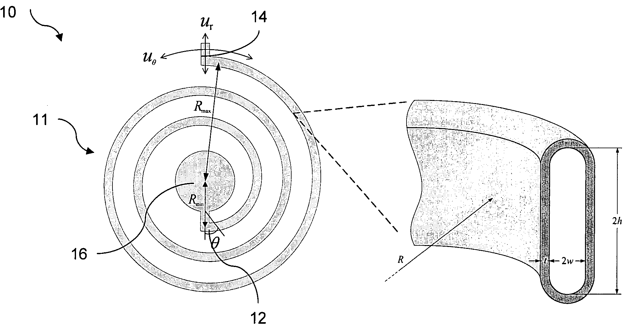
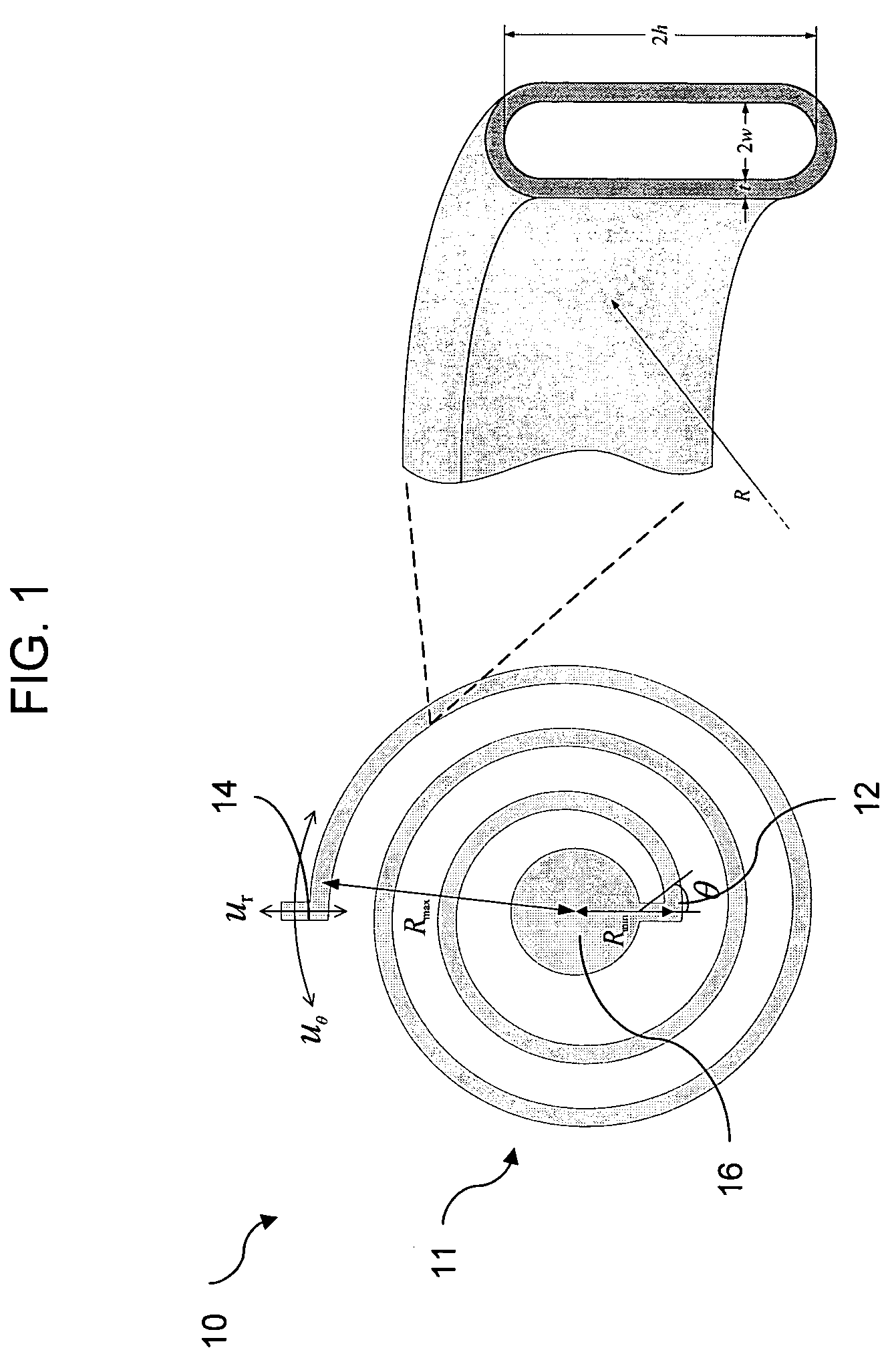
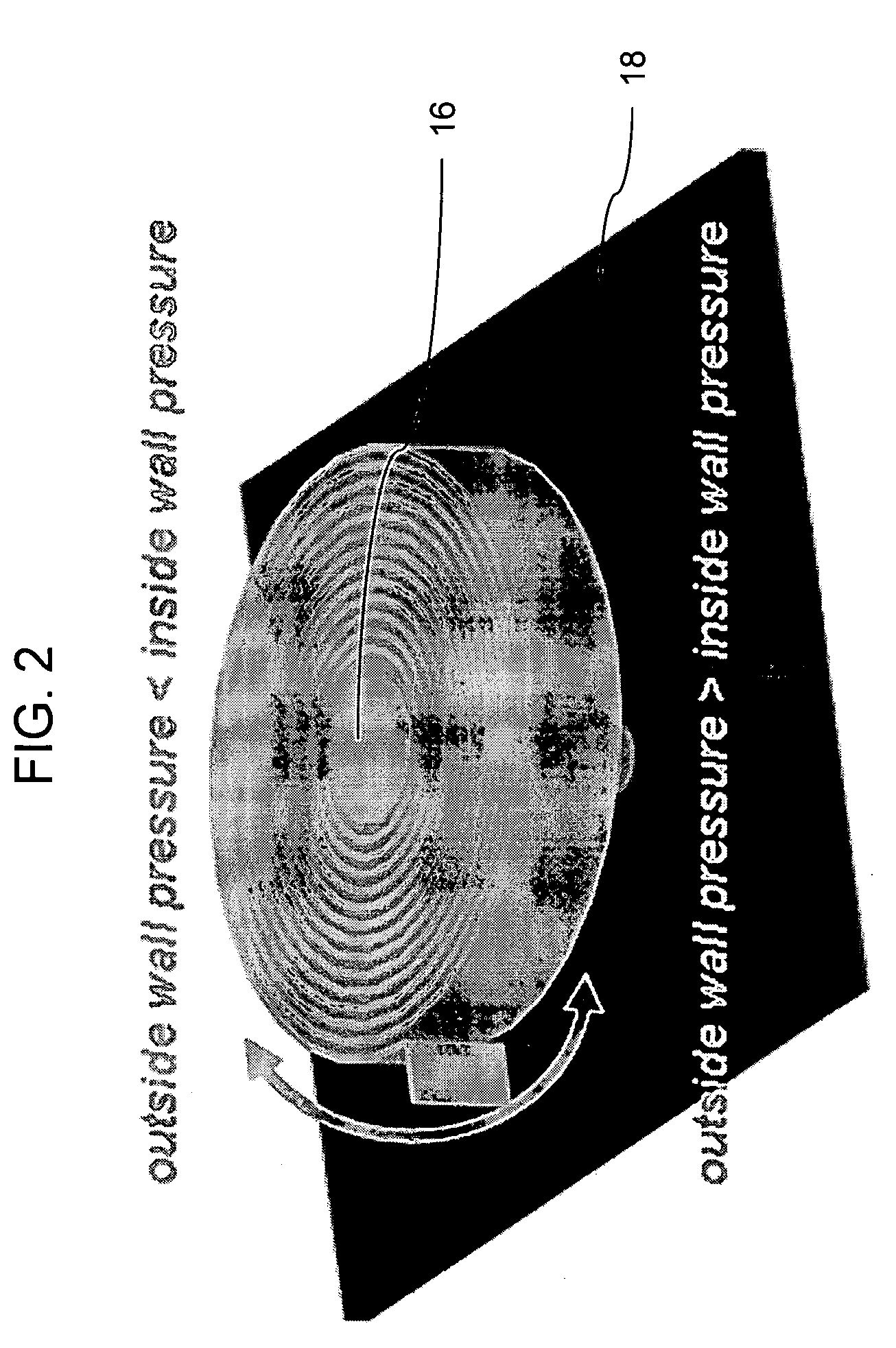
[0066]The invention can be better understood with reference to the following non-limiting examples. The testing setup used in the following examples is illustrated in FIG. 12. A system consisting of an N2 gas cylinder, a particle filter, an Airtrol R-800-60 pressure regulator, and two needle valves is used to regulate the pressure. One needle valve releases the applied pressure after each measurement. This system is connected to a closed chamber to provide different positive-applied pressures. The cap of the chamber is transparent to facilitate external optical observation. A device with a 10-turn spiral is placed inside the chamber and tested (inset to FIG. 12). When a pressure difference is applied between the outside and the inside of the channel, the pointing tip starts to rotate. This behavior is monitored through a stereoscope with 20× magnification and a mounted CCD camera to capture the image. Along with the optical readout, an OMEGA PCL100-30 pressure calibrator is also use...


PUM

PropertyMeasurementUnit
coiled angleaaaaaaaaaa
aspect ratioaaaaaaaaaa
pressureaaaaaaaaaa

Abstract

A biocompatible, mechanical, micromachined pressure sensor and methods of manufacturing such a pressure sensor are provided. The pressure sensor of the current invention includes a high-aspect-ratio curved-tube structure fabricated through a one-layer parylene process. The pressure sensor of the current invention requires zero power consumption and indicates the pressure variation by changes of the in situ in-plane motion of the sensor, which can be gauged externally by a direct and convenient optical observation. In one embodiment, the pressure sensor of the current invention has been shown to work as an IOP sensor for eye implantation where the intraocular in-plane motion of the sensor can be recorded from outside of the eye, such that the intraocular pressure in glaucoma patients can be constantly monitored.

Description

CROSS-REFERENCE TO RELATED APPLICATION(S)[0001]This application claims priority to U.S. Provisional Patent Application No. 60 / 578,052, filed Jun. 7, 2004, the disclosure of which is incorporated herein by reference.STATEMENT REGARDING FEDERALLY SPONSORED RESEARCH[0002]The U.S. Government has certain rights in this invention pursuant to grant number EEC-0310723, awarded by the National Science Foundation, Engineering Research Centers Program.FIELD OF THE INVENTION[0003]The current invention is directed to an implantable optical pressure sensors; and more particularly to an implantable mechanical intraocular pressure sensor for passive measurement of the intraocular pressure and methods of manufacturing such sensors.BACKGROUND OF THE INVENTION[0004]Glaucoma is a debilitating disease that results in loss of vision for an estimated 65 million people worldwide. Glaucoma is the second leading cause of blindness in the U.S. and the leading cause of preventable blindness. Yet, only half of ...

Claims


Application Information

Patent Timeline
Patent Type & Authority Patents(United States)
IPC IPC(8): G01L9/00A61B3/16G01L7/04G01L7/08
CPCA61B3/16G01L7/045A61B2562/02A61B2562/028
Inventor TAI, YU-CHONGMENG, ELLISCHEN, PO-JUIRODGER, DAMIEN C.HUMAYUN, MARK
Owner CALIFORNIA INST OF TECH
Why Eureka
Try Eureka