Control of vehicle drive system

a technology of drive system and control system, which is applied in the direction of electric control, manual lubrication, instruments, etc., can solve the problems of recovery shock generation, recovery shock generation, recovery shock generation, etc., and achieve the effect of preventing the generation of recovery shock

Active Publication Date: 2007-08-07
NISSAN MOTOR CO LTD
View PDF9 Cites 13 Cited by
  • Summary
  • Abstract
  • Description
  • Claims
  • Application Information

AI Technical Summary

Benefits of technology

[0009]It is therefore an object of this invention to prevent generation of a recovery shock even when fuel is cut and the air compressor is started with the lockup clutch being in an engaged state.

Problems solved by technology

Studies conducted by the inventors have shown that even in a vehicle configured to disengage the lockup clutch at a higher engine rotation speed than that for resuming fuel supply, a recovery shock may still generate when starting the air compressor in a non-driven state during the time of lowering the engine rotation speed in an engine braking state.
At this time, although fuel supply can be immediately resumed, disengagement of the lockup clutch takes some time.
As a result, since fuel supply is resumed before the lockup clutch is disengaged, a recovery shock may be generated.

Method used


Image

  • Control of vehicle drive system
  • Control of vehicle drive system
  • Control of vehicle drive system

Examples


second embodiment

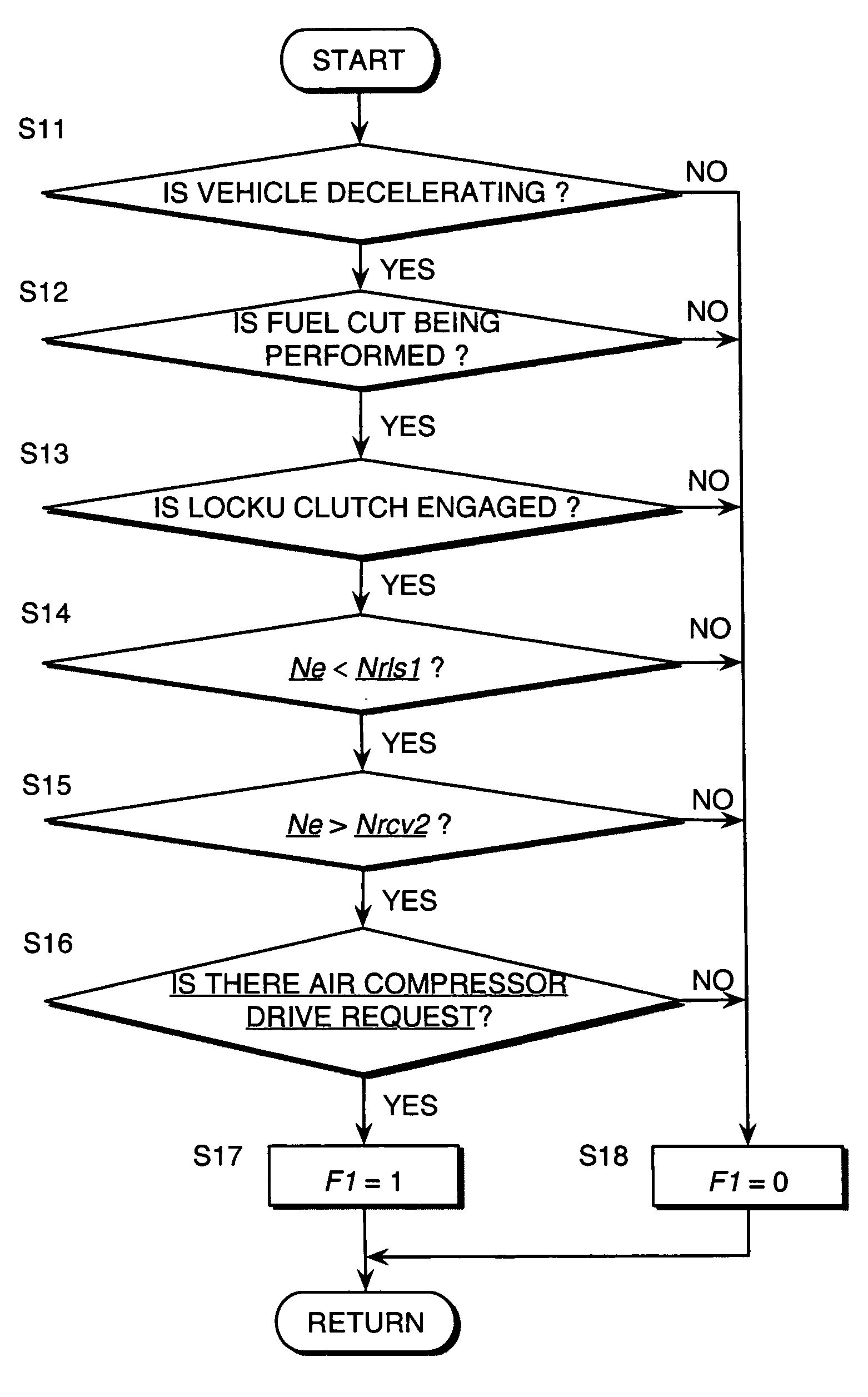
[0085]Next, referring to FIG. 6, this invention regarding a vehicle drive system control routine will be described.

[0086]This embodiment differs in that a different algorithm is used for the vehicle drive system control routine of FIG. 4 and determination as to whether or not disengagement of the lockup clutch 3 is completed. More specifically, in this embodiment, steps S21 to S23 are provided in place of the steps S5, S7 and S8 in the routine of FIG. 4. The remaining steps are the same as those in the routine of FIG. 4.

[0087]As described before, determination as to whether or not disengagement of the lockup clutch 3 has been completed is possible based on the difference between an input rotation speed Ntb of the continuously variable transmission 4 and an engine rotation speed Ne. In this embodiment, this determination algorithm is used for determination as to whether or not disengagement of the lockup clutch 3 has been completed.

[0088]The engine controller 21 carries out the follo...

first embodiment

[0093]Even with this embodiment, the same desirable results may be achieved as with the first embodiment in view of recovery shock prevention. Furthermore, with this embodiment, since disengagement completion of the lockup clutch 3 is determined based on a real difference in the rotation speeds of the rotation speed Ne of the engine 1 connected to the lockup clutch 3 and the input rotation speed Ntb of the continuously variable transmission 4, disengagement completion of the lockup clutch 3 can be more precisely determined.

[0094]The contents of Tokugan 2004-153006, with a filing date of May 24, 2004 in Japan, are hereby incorporated by reference.

[0095]Although the invention has been described above by reference to certain embodiments of the invention, the invention is not limited to the embodiments described above. Modifications and variations of the embodiments described above will occur to those skilled in the art, within the scope of the claims.

[0096]For example, in the above emb...


PUM


Abstract

An air compressor (12b) starts to operate when fuel to an internal combustion engine (1) is cut off and the engine (1) and a transmission (4) are directly engaged. Upon receiving a drive request signal, a controller (21) outputs a lockup clutch disengaging request. The controller (21) resumes fuel supply and starts driving of the air compressor (12b) only when it is confirmed that the lockup clutch (3) has been disengaged, thereby preventing a recovery shock from generating due to resumption of fuel supply during the lockup clutch (3) being in the engaged state.

Description

FIELD OF THE INVENTION[0001]This invention relates to drive force control of a vehicle, which comprises an engine that allows fuel cut and a transmission that is integrally connected to the engine via a lockup clutch.BACKGROUND OF THE INVENTION[0002]JP2001-082204A published in the year 2001 by the Japan Patent Office proposes to cut down fuel supply, namely cut fuel to the engine from a fuel supply device to economize vehicle fuel consumption when a vehicle internal-combustion engine is forced to rotate faster than a predetermined rotation speed due to the inertial force of the moving vehicle, namely in an engine braking state. If an engine rotation speed falls below a predetermined rotation speed due to the fuel cut, fuel supply is resumed.[0003]Among vehicles configured to connect the engine and the transmission via a torque converter, there is a vehicle that allows the lockup clutch to directly connect the engine and the transmission in response to a running condition, so as to s...

Claims


Application Information

Patent Timeline
Patent Type & Authority Patents(United States)
IPC IPC(8): F16H61/58B60W10/02G06F7/00F02D29/04B60H1/32F02D29/00F02D41/02F02D41/08F02N11/08
CPCF02D41/022F02D41/083F02D41/123F16N3/10Y10T477/635Y10T477/26Y10T477/79F02D2400/12
Inventor KIUCHI, HIROYUKI
Owner NISSAN MOTOR CO LTD
Why Eureka
Try Eureka