
Heart valve structures

a heart valve and structure technology, applied in the field of heart valve structures, can solve the problems of shortening the life of the stented valve, unnecessary wear, tearing or calcification, etc., and achieve the effect of high degree of flexibility

Inactive Publication Date: 2007-08-07
ST JUDE MEDICAL LLC
View PDF31 Cites 21 Cited by
  • Summary
  • Abstract
  • Description
  • Claims
  • Application Information

AI Technical Summary

Benefits of technology

[0008]The support structure or structures provided in heart valves in accordance with this invention are preferably much more flexible than the stents typically provided in stented heart valves. For example, the supports provided in accordance with this invention may be characterized as providing “minimal” support. This amount of support may be described as sufficient to keep various parts of the tissue structure in their natural (native) relative positions during implantation of the valve in a patient and in the absence of significant external distorting force. However, the amount of support provided is preferably not significantly greater than the minimum amount required to accomplish the objectives described in the preceding sentence. The valves of this invention therefore have a very high degree of flexibility, which may be slightly less than the flexibility of a completely unsupported valve, but much greater than the flexibility of typical stented or mechanical valves.

Problems solved by technology

The commissure posts of the valve are typically relatively long and flexible, and if they are not pinned back, they can fold over onto the valve leaflets in an undesirable way (e.g., impacting the leaflets and causing unnecessary wear).
Such valves may compare favorably to the more rigid valves known as “stented” valves in respects such as the following: The rigidity of stented valves may stress the leaflets in the valve, which can cause tearing or calcification of the leaflets, which in turn can shorten the life of a stented valve.
However, the stentless valves described above are thought by some to be somewhat more difficult to implant than stented valves or mechanical valves.
Also, the high degree of flexibility of stentless valves can allow the commissure posts of the valve to fold down in the surgeon's way during placement of the first (inflow) suture line, and / or to permit one or more of those posts to be slightly mislocated when the final (outflow) suture line is made, with the possible result that the finally implanted valve may not close as completely and perfectly as it otherwise would.

Method used


Image

  • Heart valve structures
  • Heart valve structures
  • Heart valve structures

Examples


Embodiment Construction

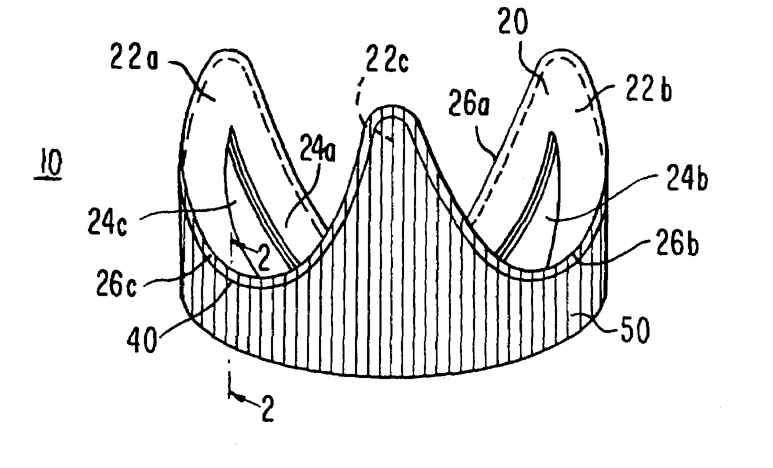
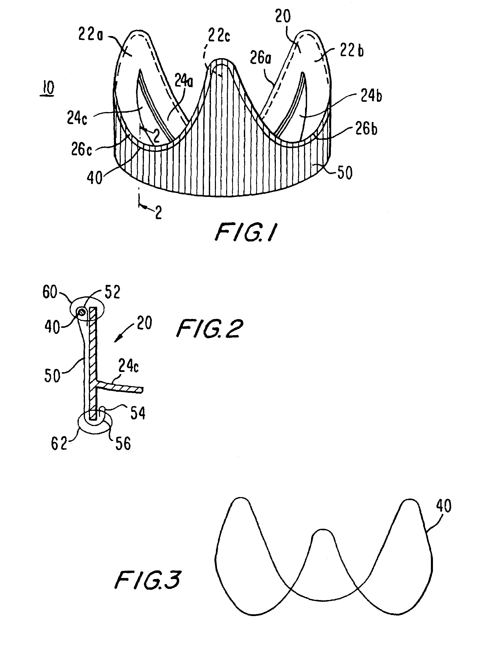
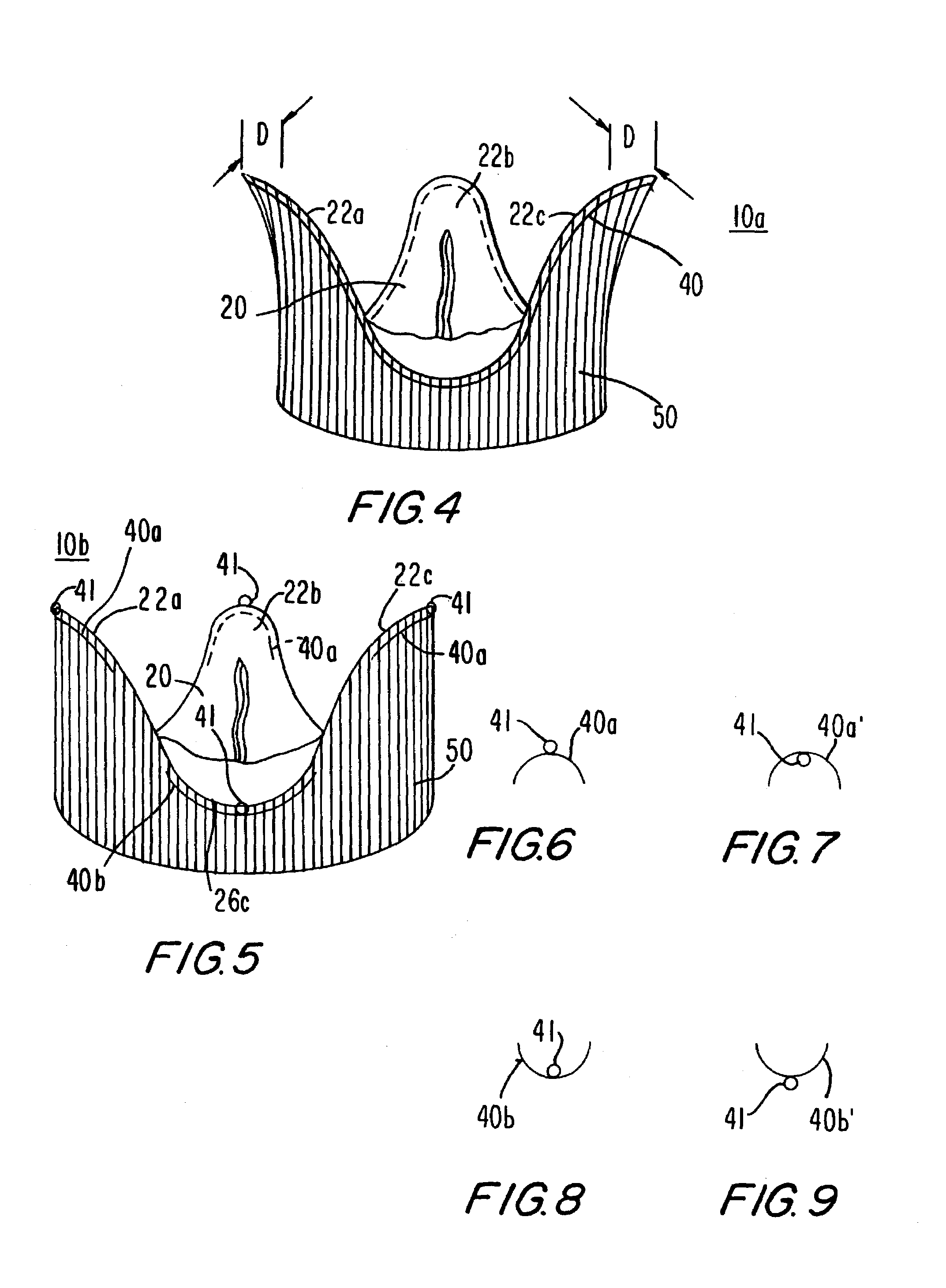
[0029]In the illustrative replacement heart valve structure 10 shown in FIG. 1, component 20 is a harvested and preserved, intact, porcine heart valve. The porcine heart valve is an annular tissue structure and includes three commissure posts 22a, 22b, and 22c, and three valve leaflets 24a, 24b, and 24c. This tissue structure has been harvested and preserved in a a conventional manner. In the illustrative embodiment shown in FIG. 1, the bottom (blood inflow) edge of the tissue is a relatively straight annulus. In other embodiments the inflow edge may be scalloped. (Such scalloped inflow edges are shown in some of the later-described embodiments.) The upper (blood outflow) edge is deeply scalloped to leave the three commissure posts 22 and valve leaflets 24 intact, but to cut away porcine aortic root tissue that is not needed between the commissure posts. The reference numbers 26a, 26b, and 26c are applied to the three recesses that result from this scalloping between commissure post...


PUM


Abstract

A replacement heart valve structure including a structure of tissue which is an intact, mammalian heart valve that has been harvested and treated to preserve it. A conventional fabric sleeve is typically disposed concentrically around the outside of the tissue structure. A support structure is included to facilitate implanting the heart valve by somewhat increasing the stability of the heart valve structure, but without unduly rigidifying it. An annular sewing cuff may be added adjacent the blood inflow end of the valve structure to facilitate making the annular suture line that is required at that end.

Description

[0001]This application claims the benefit of U.S. provisional patent application 60 / 357,166, filed Feb. 14, 2002, which is hereby incorporated by reference herein in its entirety.BACKGROUND OF THE INVENTION[0002]One of the known techniques for replacing a heart valve in a human patient is to use a valve harvested from another mammal. Although the invention will be described for the most part with reference to replacing a patient's aortic valve (i.e., the valve between the left ventricle and the aorta), the principles of the invention can be adapted to other heart valve replacement procedures. Similarly, although heart valves harvested from pigs (porcine heart valves) are generally used, valves harvested from other mammals are possible alternatives.[0003]In a known technique, a heart valve is harvested intact from a pig and treated to preserve it. (All references herein to such heart valves will be understood to include the immediately adjacent tissue, so that the structure thus refe...

Claims


Application Information

Patent Timeline
IPC IPC(8): A61F2/24
CPCA61F2/2412A61F2/2418A61F2220/0075
Inventor BERG, TODD APETERSON, ALEX AWESTON, MATTHEW W
Owner ST JUDE MEDICAL LLC
Learn More