Flue gas conversion apparatus and method

a technology of gas conversion apparatus and flue gas, which is applied in the direction of lighting and heating apparatus, emission prevention, separation processes, etc., can solve the problems of affecting the efficiency of the apparatus, so as to reduce the energy penalty of operating the apparatus

Inactive Publication Date: 2007-08-07
PET PROJECTS
View PDF4 Cites 26 Cited by
  • Summary
  • Abstract
  • Description
  • Claims
  • Application Information

AI Technical Summary

Benefits of technology

[0008]It is yet another object of the invention to create other useful products from t

Problems solved by technology

However this recent addition by anthropogenic sources, such as industrial processes which rely upon the burning of fossil fuels, has increased the concentration of CO2 in the atmospheric makeup to the point where certain adverse effects are now apparent.
The most obvious effect is a phenomena known as “greenhouse effect”, a potentially dangerous phenomena which if left unchecked could possibly reap catastrophic consequences upon the human race.
It is als

Method used


Image

  • Flue gas conversion apparatus and method
  • Flue gas conversion apparatus and method
  • Flue gas conversion apparatus and method

Examples


Embodiment Construction

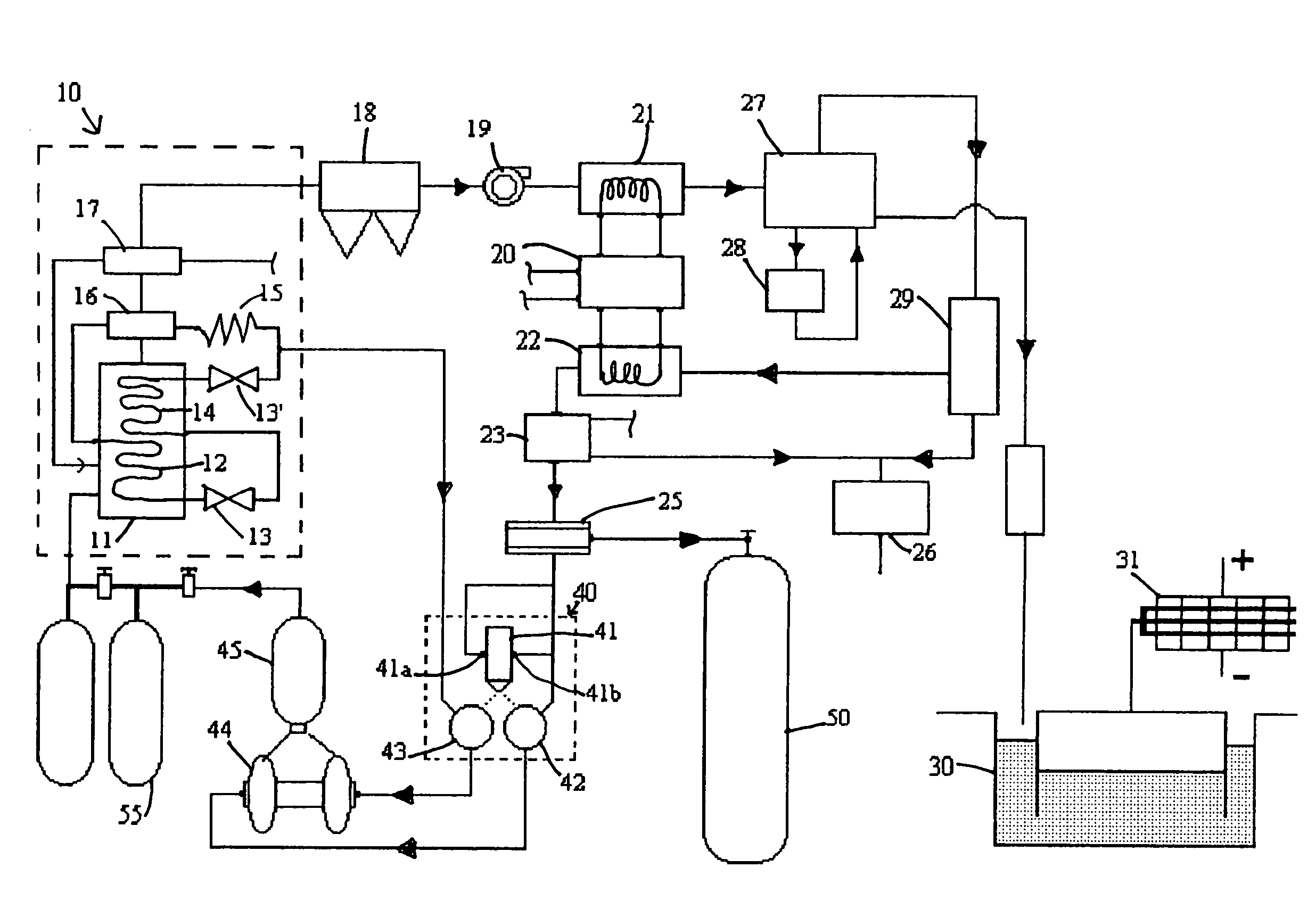
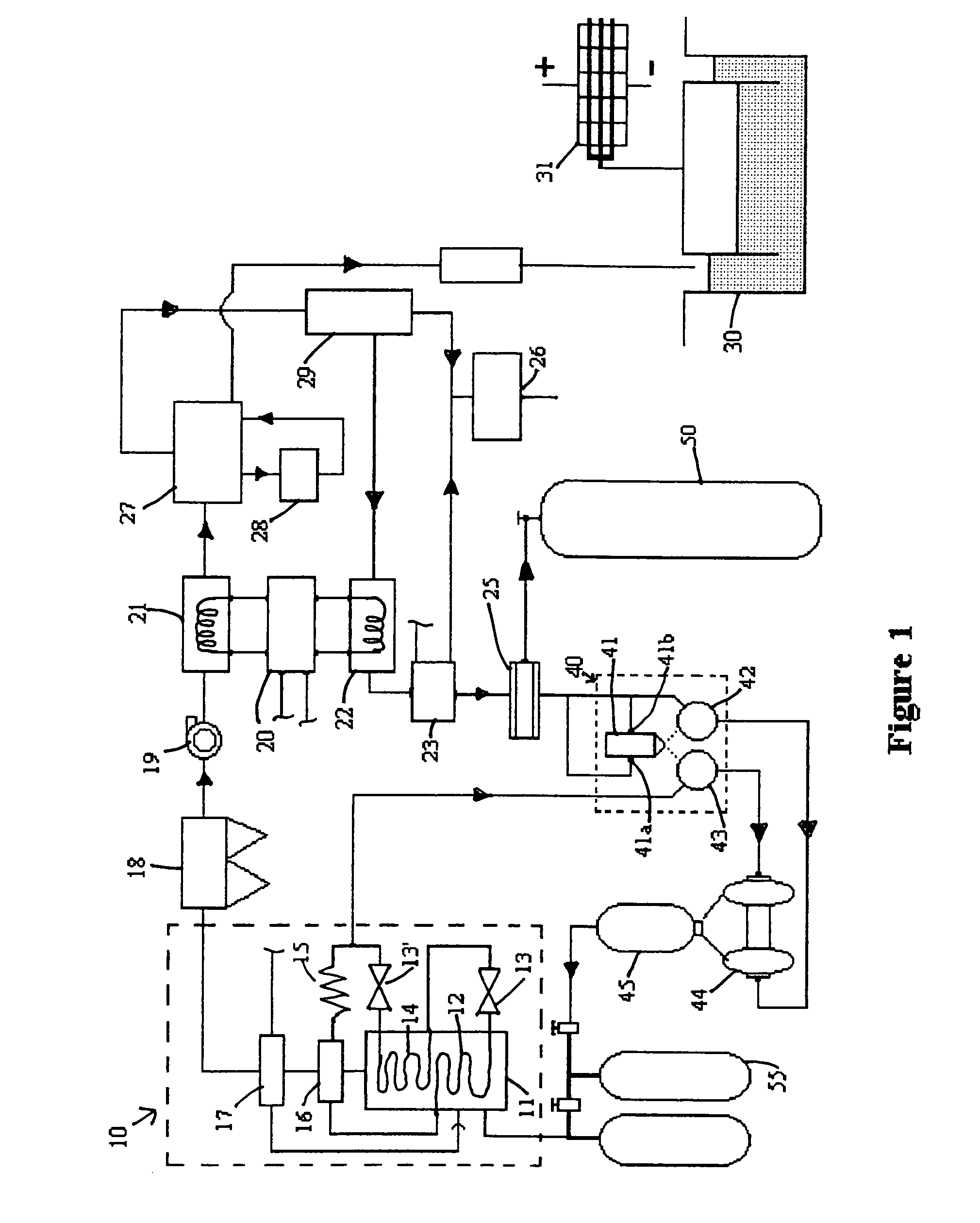
[0015]With reference to FIG. 1 a flue gas source 10 is depicted including furnace 11 wherein fuel mixed with air and burned. The conventional components of the furnace are shown as boiler superheater 12, steam turbine 13, intermediate turbine 13′, secondary superheater 14, condenser 15, economizer 16, and air heater 17. The resultant flue gas is made to enter cyclone 18 wherein particulate matter is removed. If the fuel being burned is not coal, then 18 can be eliminated. Induction fan 19 draws the flue gas, which has a temperature of approximately 355 degrees Fahrenheit, out of the furnace and forces it into high temperature heat exchanger 21. Heat exchanger 21 which uses water as the exchange medium lowers the temperature of the gas to approximately 175 degrees Fahrenheit while simultaneously producing steam to drive lithium bromide chiller 20 which in turn produces forty degree water. Chiller 20 consumes 0.006% of power plant output (PPO). Upon exiting the heat exchanger the flue...


PUM


Abstract

An apparatus and method of converting flue gases produced by a fossil fuel burning furnace boiler is disclosed. The flue gas is separated into its constituent parts by cooling and filtering. Carbon dioxide, the main constituent, is then converted to carbon monoxide in a laser powered gas converter in which carbon is a catalyst. The laser powered converter also produces hydrogen from steam, and the two newly produced gases are chemically combined to produce a hydrocarbon fuel product which can then be burned in the furnace boiler. In this manner no harmful greenhouse gases are permitted to escape to the atmosphere.

Description

BACKGROUND OF THE INVENTION[0001]1. Field of the Invention[0002]The present invention relates to an apparatus and method of utilizing the flue gas mixture produced from burning fossil fuels, particularly the gaseous carbon dioxide constituent of the mixture, thereby eliminating the release of greenhouse gases into the earth's atmosphere.[0003]2. Description of the Related Art[0004]A recently discovered consequence of our industrial age is an increase of the concentration of carbon dioxide (CO2), a trace element in our Earth's atmosphere. It is known that just before the industrial revolution the CO2 content of the atmosphere was 280 parts per million (ppm). In 1989 the CO2 content was a little over 350 ppm. This increase in a relatively short period of time is an apparent indication that an overload condition exists upon elements which behave as natural sinks for this gas. These elements, namely the oceans, vegetation, and rocks have so far been able to function perfectly as natural...

Claims


Application Information

Patent Timeline
IPC IPC(8): B01J8/02B01J19/08F01N3/10
CPCB01D53/62B01D53/864F23J15/006B01D2257/504F23J2215/50F23J2219/10Y02C10/04Y02A50/20Y02C20/40Y02E20/32
Inventor MERRITT, THOMAS D.
Owner PET PROJECTS
Why Eureka
Try Eureka