Organic materials for an evaporation source

a technology of organic materials and evaporation sources, applied in vacuum evaporation coatings, chemical vapor deposition coatings, coatings, etc., to achieve the effect of making organic layers

Active Publication Date: 2007-08-07
GLOBAL OLED TECH
View PDF16 Cites 17 Cited by
  • Summary
  • Abstract
  • Description
  • Claims
  • Application Information

AI Technical Summary

Benefits of technology

[0025]A feature of the present invention is that the effectiveness of pellets of organic material including a mixture of a host and at least one dopant can be determined prior to making such pellet.
[0026]Another feature of the present invention is that compacted pellets made in accordance therewith can be used in a single evaporation source to effectively make organic layers. The effectiveness of such a mixture is that a homogeneous deposition of materials can be deposited, ensuring that the formed organic layer provides its intended function.

Problems solved by technology

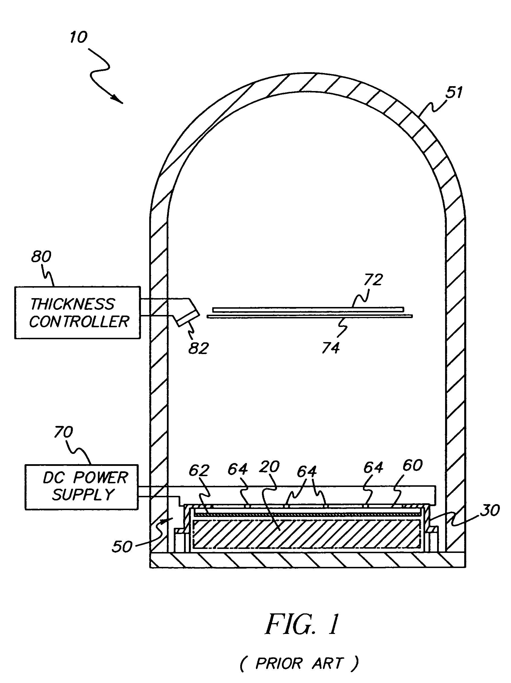
Several problems have been observed in using organic powders, flakes, or granules in physical vapor deposition:(i) powders, flakes, or granules are difficult to handle because they can acquire electrostatic charges via a process referred to as triboelectric charging;(ii) powders, flakes, or granules of organic materials generally have a relatively low physical density (expressed in terms of weight per unit volume) in a range from about 0.05 to about 0.2 g / cm3, compared to a physical density of an idealized solid organic material of about 1 g / cm3;(iii) powders, flakes, or granules of organic materials have an undesirably low thermal conductivity, particularly when placed in a physical vapor deposition source which is disposed in a chamber evacuated to a reduced pressure as low as 10−6 Torr.
In using the thermal physical vapor deposition source disclosed by Spahn to form an organic layer of a selected organic material on a substrate or structure, it has been found that the vapor efflux slit-aperture causes non-uniform vapor flux of organic material to emanate along a length dimension of the slit.
There is a problem when the width dimension of the slit is reduced, for example, to a width dimension less than 0.5 mm.
Such non-uniform vapor flux, directed at a substrate or structure, will cause the formation of an organic layer thereon which will have a non-uniform layer thickness in correspondence with the non-uniform vapor flux.
In addition, any nonuniformities in heat generation from the heater or heat absorption by the material to be deposited or distribution of the material within the source can give rise to nonuniformity in deposition along the length of the source.
Yet another source of nonuniformity is unintended leaks in the source enclosure other than the apertures used to deliver the organic vapor.
If such leak exists at the ends of the source., the flow of vapor from center to end of the source can cause pressure gradients within the source, thereby causing nonuniformity in the resultant deposition.
This problem becomes even more critical when contemplating the use of inorganic materials that vaporize to the desired extent at substantially higher temperatures.
It is possible that compacted pellets using a mixture of two organic materials wherein one organic component has substantially a lower sublimation temperature as compared to the other organic component, will be prone to depletion of that organic component having lower sublimation temperature in a relatively short time.
Markedly different sublimation temperatures of the organic components may render the compacted pellets unusable in a manufacturing environment because the evaporation sources are used continuously for hours in making OLED displays.
Each one, or a combination, of the aforementioned aspects of organic powders, flakes, or granules can lead to nonuniform heating of such organic materials in physical vapor deposition sources with attendant spatially nonuniform sublimation or vaporization of organic material and can, therefore, result in potentially nonuniform vapor-deposited organic layers formed on a structure.

Method used


Image

  • Organic materials for an evaporation source
  • Organic materials for an evaporation source
  • Organic materials for an evaporation source

Examples


example 1

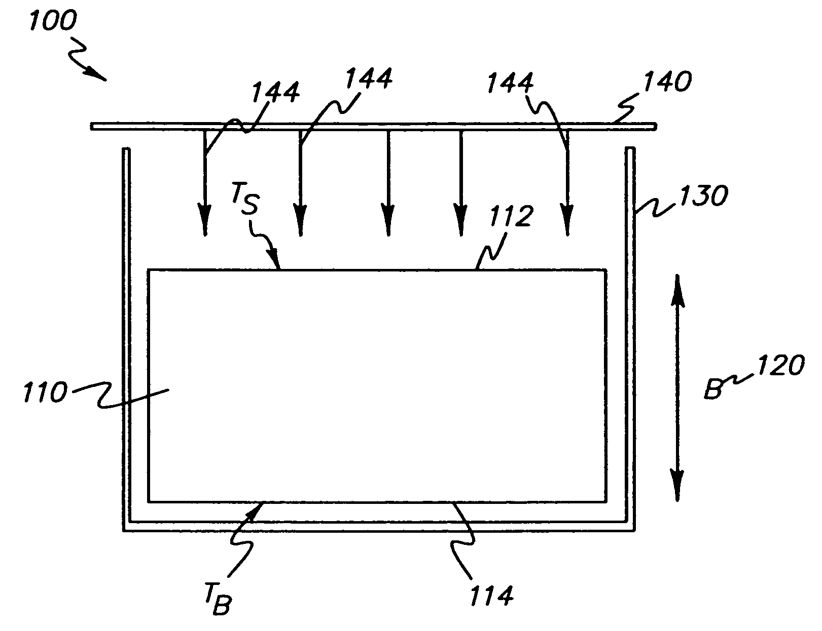
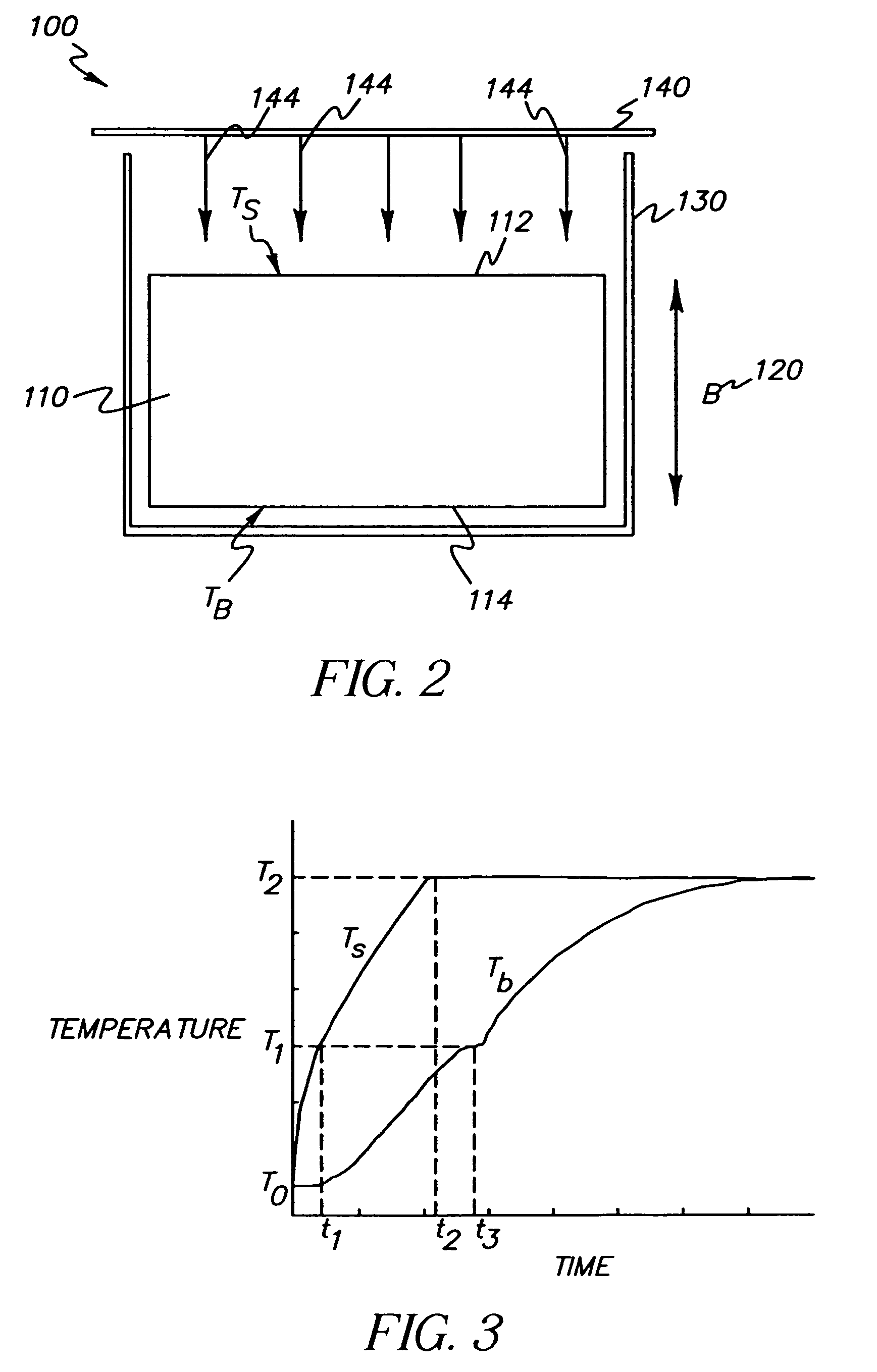
[0059 is shown graphically in FIG. 6. The physical parameters used in this example are typical for OLED materials and those parameters may be treated as a baseline for Examples 2 through 8. The heat flux, 0.1 W / cm2, results in the usage of 80%. Examples 2 through 8 show how the numerical value of M and as a result the usage of the compacted pellet changes drastically from those in Example 1 if only a few parameters are varied slightly. The examples in Table 1 therefore suggest that one can predict very precisely the performance of a single evaporation source well ahead of the deposition process.

example 2

[0060 is presented graphically in FIG. 7. In this case, the sublimation temperature of the dopant component is 150° C. instead of 200° C. and all other parameters are exactly the same as in Example 1. The usage is decreased to 77%. An increase in the difference in sublimation temperatures between the host and dopant components will tend to decrease the usage of a compacted pellet.

[0061]Example 3 is presented graphically in FIG. 8. In this case, the only parameter changed is the heat flux applied to the compacted pellet which is 0.05 W / cm2 as compared to 0.1 W / cm2 as in Example 2. The usage is decreased to 65%. A decrease in applied heat flux will decrease the usage.

[0062]Example 4 is shown graphically in FIG. 9. In this case, the heat flux applied to the pellet is 0.2 W / cm2 and all other parameters are the same as in Example 2. The usage is increased to 86%. An increase in applied heat flux from the top surface while other physical parameters remain the same for a compacted pellet r...


PUM

PropertyMeasurementUnit
physical densityaaaaaaaaaa
vertical lengthaaaaaaaaaa

Abstract

A method of using a compacted pellet having uniform blended mixture with at least first and second different organic components that sublime at temperatures T1 and T2 respectively, wherein T1 represents the temperature of the first organic material with the lowest sublimation temperature and T2 represents the temperature of the second organic material with the highest sublimation temperature, to form an organic layer having a uniform blended mixture of the organic components, includes providing a compacted pellet, having a top and bottom surface, into a boat having an open top surface wherein the compacted pellet conforms to the interior of the boat; and applying heat to the top of the compacted pellet to cause the deposition of a uniform blended mixture of the organic components to form an organic layer.

Description

CROSS REFERNCE TO RELATED APPLICATIONS[0001]Reference is made to commonly assigned U.S. patent application Ser. No. 10 / 384,290 filed Mar. 7, 2003 entitled “Making and Using Compacted Pellet for OLED Displays” by Ghosh et al., and U.S. patent application Ser. No. 10 / 624,311 filed Jul. 22, 2003 entitled “Thermal Physical Vapor Depositions Source Using Pellets of Organic Material for Making OLED Displays” by Klug et al, the disclosures of which are incorporated herein by reference.FIELD OF THE INVENTION[0002]The present invention relates to using a compacted pellet of organic materials including a host and at least one dopant mixed therein to form an organic layer. More particularly, this invention relates to using a compacted pellet of mixed organic materials wherein such compacted pellet is used in a single evaporation source in a physical vapor deposition process.BACKGROUND OF THE INVENTION[0003]An organic light-emitting diode (OLED), also referred to as an organic electroluminescen...

Claims


Application Information

Patent Timeline
Patent Type & Authority Patents(United States)
IPC IPC(8): C23C16/00
CPCC23C14/12C23C14/26H01L51/0008H01L51/001H01L51/56H10K71/16H10K71/164H10K71/00
Inventor NG, KAM C.GHOSH, SYAMAL K.SWITALSKI, STEVEN C.
Owner GLOBAL OLED TECH
Why Eureka
Try Eureka